Waste treatment apparatus

a technology of waste treatment and equipment, applied in the direction of biomass after-treatment, transportation and packaging, rotary stirring mixers, etc., can solve the problems of reducing the efficiency of agitating raw waste and other waste in the main body, raw waste and other waste cannot be agitated uniformly and efficiently, and the efficiency of agitating raw waste and other waste is not always high, so as to achieve efficient agitation and efficient agitation

Inactive Publication Date: 2010-10-19
KOAI IND
View PDF14 Cites 7 Cited by
  • Summary
  • Abstract
  • Description
  • Claims
  • Application Information

AI Technical Summary

Benefits of technology

[0018]The heat of the exhaust-heat gas deodorized by the deodorization device assists the heating of the treatment tank through the assisting device. Therefore, the entire treatment tank is efficiently heated.
[0022]According to experiments performed by the present inventor, when the inclination angle of the blade with respect to the paddle arm is set within the range of about 1° to about 15°, the waste is more efficiently agitated and is effectively ground between the blade and the inner wall of the treatment tank to divide the waste into small pieces.
[0023]With the waste treatment apparatus according to preferred embodiments of the present invention, waste including plastic waste, raw waste, paper waste, and other waste can be subjected to volume reduction-annihilation treatment by decomposing the waste by microorganisms while these types of waste are efficiently agitated together. Therefore, for example, raw waste and / or paper waste is not required to be separated from waste such as plastics, and thus these waste can be treated together. Hence, with the waste treatment apparatus according to the present invention, in contrast to a conventional waste treatment apparatus, little effort is required to separate waste, and thus the effects is more apparent.

Problems solved by technology

However, when the agitating elements, such as paddles, used in such a conventional waste treatment apparatus (see, for example, FIGS. 2 and 3 of Patent Document 1) are used, the efficiency of agitating raw waste and other waste in a main body is not always high even if the organic waste is crushed by a crusher and then fed into the main body.
For example, a bridge phenomenon occurs in which the end portion of a puddle carries ball-like clusters of raw waste and other waste, and thus the raw waste and other waste cannot be agitated uniformly and efficiently.
Therefore, the efficiency of agitating raw waste and other waste is reduced, and a problem occurs in that decomposition treatment (fermentation treatment) by microorganisms takes a very long time.
In such a conventional waste treatment apparatus, the problem described above occurs even when only the so-called raw waste, such as food scraps and leftovers, is treated.
Therefore, when raw waste is agitated in the main body together with plastic waste including plastic bags and plastic packaging containers such as styrofoam trays and / or paper waste such as newspaper, corrugated cardboard, and paper diapers, the agitation efficiency is further reduced.
That is to say, such a conventional waste treatment apparatus is not suitable for simultaneously subjecting waste including raw waste mixed with plastic waste and paper waste to decomposition treatment (fermentation treatment) by microorganisms.
Therefore, in such a conventional waste treatment apparatus, at least plastic waste must be separated from raw waste and / or paper waste, and thus a lot of effort is required.

Method used


Image

  • Waste treatment apparatus
  • Waste treatment apparatus
  • Waste treatment apparatus

Examples


Embodiment Construction

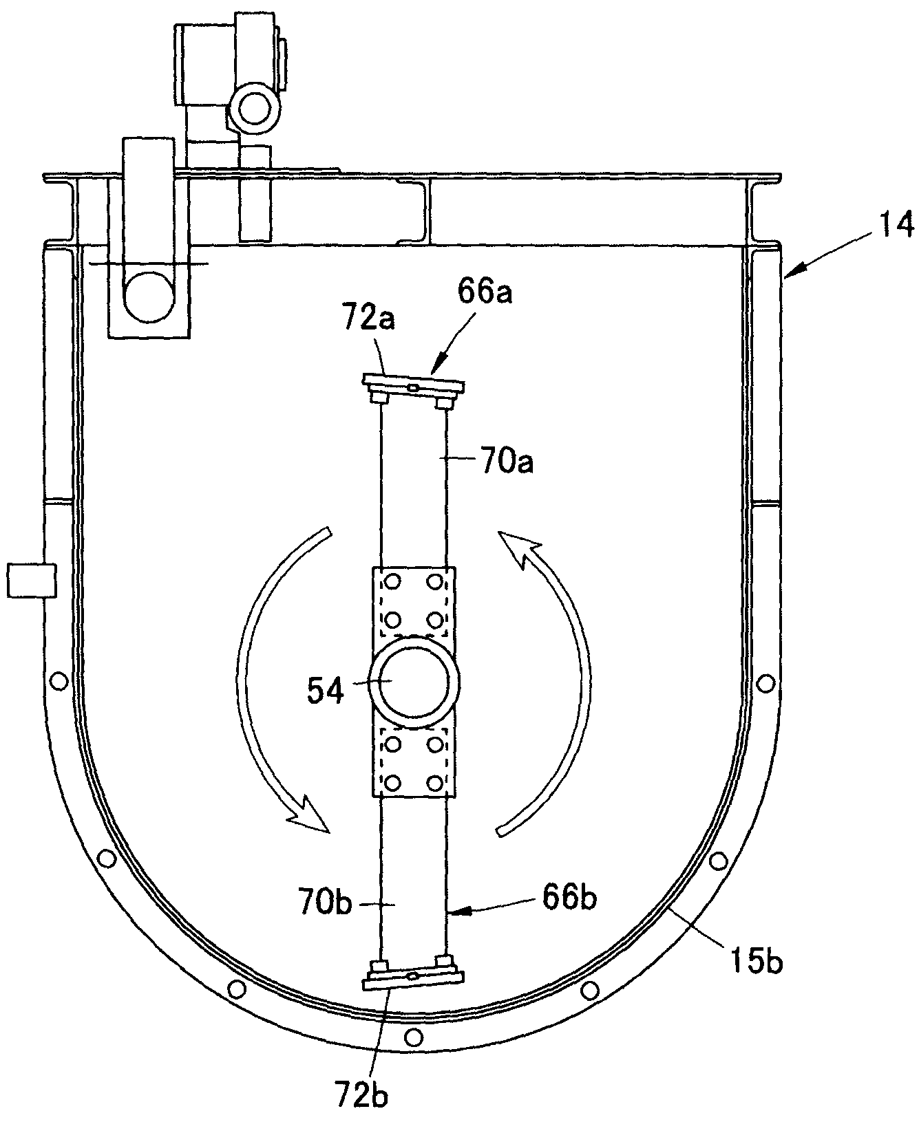
[0055]In the waste treatment apparatus according to preferred embodiments of the present invention, subjecting waste including plastic waste, raw waste, waste such as paper, and other types of waste to volume reduction-annihilation treatment by decomposing the waste by microorganisms while the waste is efficiently agitated together can be achieved without separating, for example, raw waste and / or waste such as paper from waste such as plastic, in contrast to a conventional apparatus.

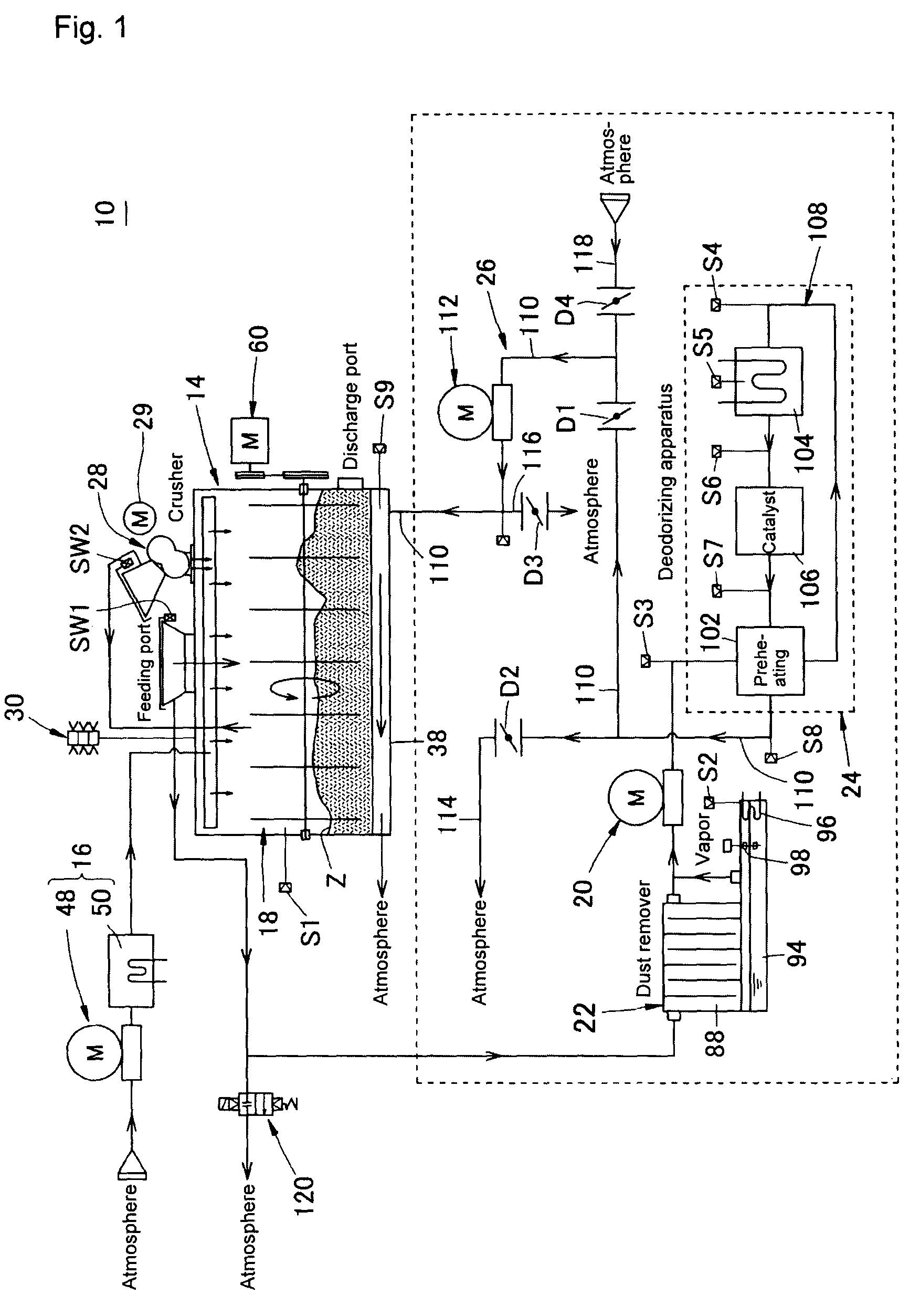
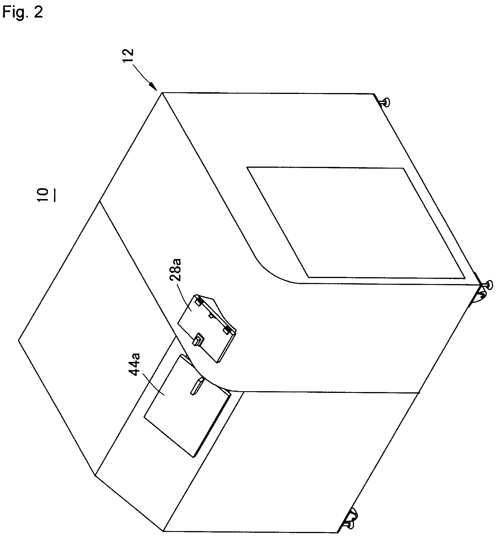
[0056]FIG. 1 is a flow diagram illustrating an example of a preferred embodiment of the waste treatment apparatus according to the present invention, and FIG. 2 is an outside view illustrating the example of the preferred embodiment of the waste treatment apparatus according to the present invention. FIG. 3 is a plan view illustrating the example of the preferred embodiment of the waste treatment apparatus according to the present invention, FIG. 4 is a front view thereof, FIG. 5 is a right side view the...


PUM

PropertyMeasurementUnit
inclination angleaaaaaaaaaa
thicknessaaaaaaaaaa
temperatureaaaaaaaaaa

Abstract

A waste treatment apparatus decomposes waste by the microorganisms to perform annihilation treatment. The waste treatment apparatus includes a treatment tank which accommodates the microorganisms together with the waste, and an agitation device arranged to agitate the microorganisms together with the waste. The agitation device includes a plurality of agitating tools arranged at predetermined intervals in the axial direction of a rotation shaft. The agitating tools have paddle arms, respectively, which are disposed so as to be opposed to each other in a diameter direction of the rotation shaft, and blades, respectively, which are disposed at predetermined distances apart from an inner wall of the treatment tank and are inclined with respect to the axis of the paddle arms. The blade on one side is inclined forward in a direction in which the front side thereof with respect to the rotation direction of the paddle arm approaches the rotation shaft. The blade on the other side is inclined backward in a direction in which the rear side thereof with respect to the rotation direction of the paddle arm 70b approaches the rotation shaft.

Description

BACKGROUND OF THE INVENTION[0001]1. Field of the Invention[0002]The present invention relates to a waste treatment apparatus. In particular, the present invention relates to a waste treatment apparatus for performing volume reduction-annihilation treatment by decomposing, by microorganisms, various raw waste such as vegetables, meats, and fishes, various plastic waste such as plastic bags and foamed trays, various paper waste such as paper bags, paper cartons, corrugated cardboard, newspaper, and paper diapers, and other waste.[0003]2. Description of the Related Art[0004]An organic waste treatment apparatus is been disclosed in Japanese Patent Laid-Open Publication No. Hei 9-1112 (Patent Document 1). In this organic waste treatment apparatus, microorganisms are added to organic waste, such as raw waste (leftovers, noodles, fishes, vegetable scraps, meats, fruits, chicken egg shells, fish bones, etc.), and the organic waste is decomposed into water and carbonic acid gas in a main bod...

Claims


Application Information

Patent Timeline
Patent Type & Authority Patents(United States)
IPC IPC(8): C12M1/00B01F5/06B01F7/02B01F7/04B09B3/00C05F17/02
CPCB01F5/0603B01F7/022B01F7/04B09B3/00C05F17/0223Y02P20/145Y02W30/43B01F2215/0042C05F17/929Y02W30/40B01F25/421B01F27/62B01F27/70B01F2101/25
Inventor NOMURA, TOKUMITSU
Owner KOAI IND
Why Eureka
Try Eureka