Method and apparatus for severing disks of brittle material, in particular wafers

a technology of brittle material and severing disk, which is applied in the direction of laser beam welding apparatus, glass making apparatus, electric beam welding apparatus, etc., can solve the problems of insufficient severing edge precision, less than 500 m, and frequent termination of severing cracks, etc., and achieves great precision

Inactive Publication Date: 2010-10-19
3D MICROMAC AG
View PDF21 Cites 0 Cited by
  • Summary
  • Abstract
  • Description
  • Claims
  • Application Information

AI Technical Summary

Benefits of technology

[0020]It is the primary object of the invention to find a severing method based on the principle of inducing thermal stresses by laser in which the disk 1 to be severed does not come into contact with a liquid coolant and severing edges can be cut with great precision.
[0025]As a result of the time delay between the laser beam and coolant jet in DE 693 04 194 T2 caused by a minimum distance between the laser beam and coolant jet, the heating zone expands not only over the depth of the disk but also over its width due to the heat conduction and, secondly, the temperature decreases again along the severing line. However, in the method according to the invention there is no time delay between the introduction of heat and the removal of heat. Therefore, a very high temperature gradient can be generated and, depending on the beam width of the laser beam 5, can be localized very narrowly on the severing lines. The method can be applied in an advantageous manner particularly for very thin disks 1, e.g., sapphire wafers, which can be cooled very quickly to the desired cooling temperature along the severing lines and in which the distances between cuts are very small.
[0027]For technical reasons having to do with the subsequent separation of the chip, the disk 1 can be glued to a stretch foil 4 so that the disk 1 is placed on the cooled supporting surface 2 with the intermediary of the stretch foil 4. This supporting surface 2 should be as thin as possible without impairing its actual function and should have excellent heat conductivity.
[0031]However, cooling the entire disk volume has the advantage that the temperature of the disk 1 can be detected by means of a contacting or noncontacting temperature gauge in order to regulate the cooling in such a way that a process temperature can be adjusted which can always be identically reproduced when processing the disks 1.
[0033]A surface cooling or a locally confined partial cooling can also be preceded by cooling over the entire surface, e.g. by means of circulating gases. This can reduce the actual active process time during which the disk 1 lies on the supporting surface 2, particularly for thicker disks 1 in which a uniform cooling over the thickness of the disk proceeds relatively slowly because of the poor thermal conductivity of the brittle material. To this end, the disks 1 can be held in a cooled storage prior to the severing process or can be supplied to the workpiece holder 3 via a cooling antechamber.

Problems solved by technology

Practical trials have shown that the precision of the severing edges that can be achieved with this method when severing a disk in very narrow strips or chips, e.g., less than 500 μm, is insufficient.
A method according to WO 03 / 018276 is disadvantageous in that it also compulsorily requires a liquid coolant.
Compared to a method according to DE 693 04 194 T2, a method according to WO 03 / 018276 also has the disadvantage that the tensile stresses and the compressive stresses only form at the surface and therefore the severing crack frequently terminates as a blind crack in the volume of the material.

Method used


Image

  • Method and apparatus for severing disks of brittle material, in particular wafers
  • Method and apparatus for severing disks of brittle material, in particular wafers

Examples


Embodiment Construction

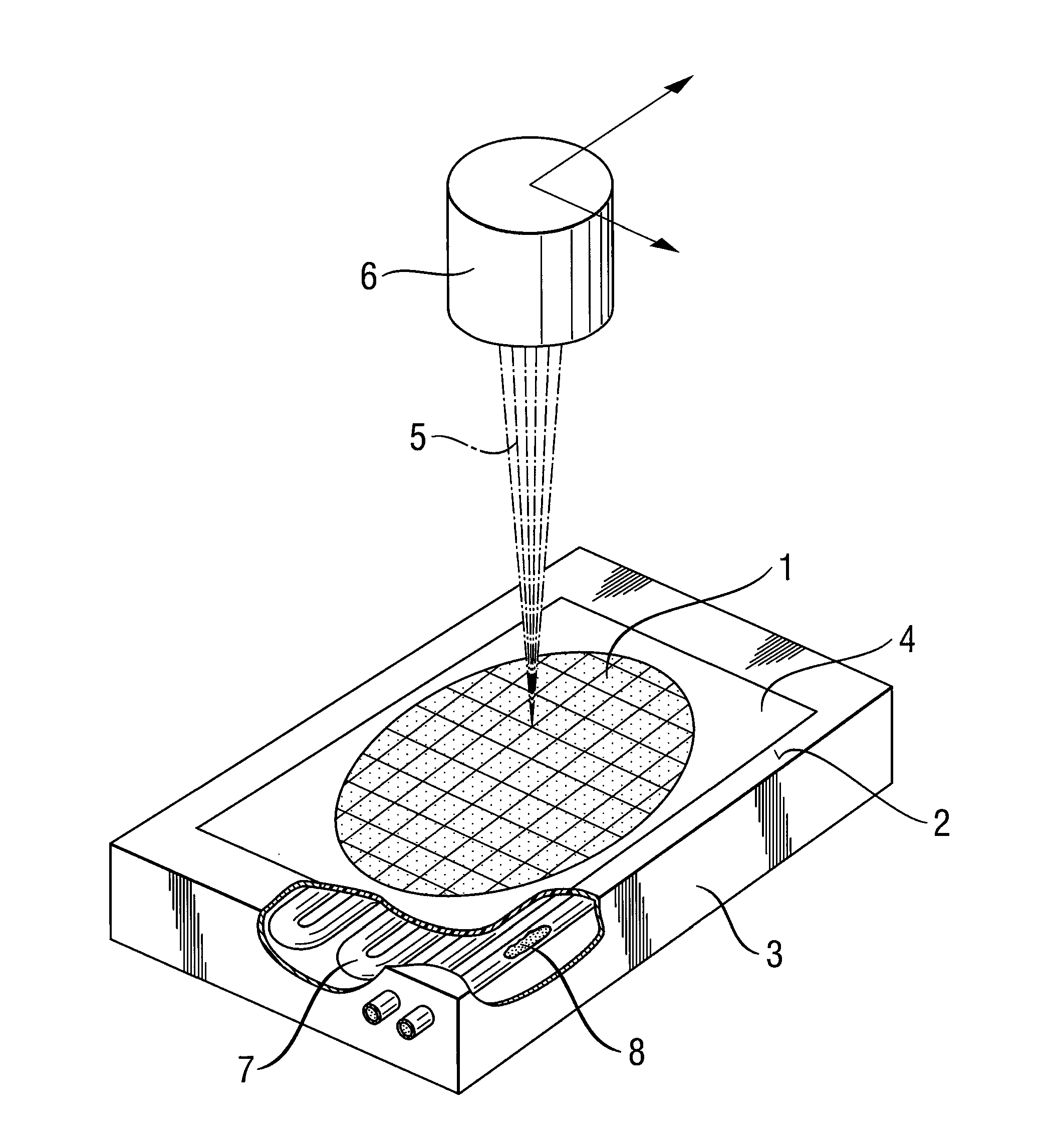
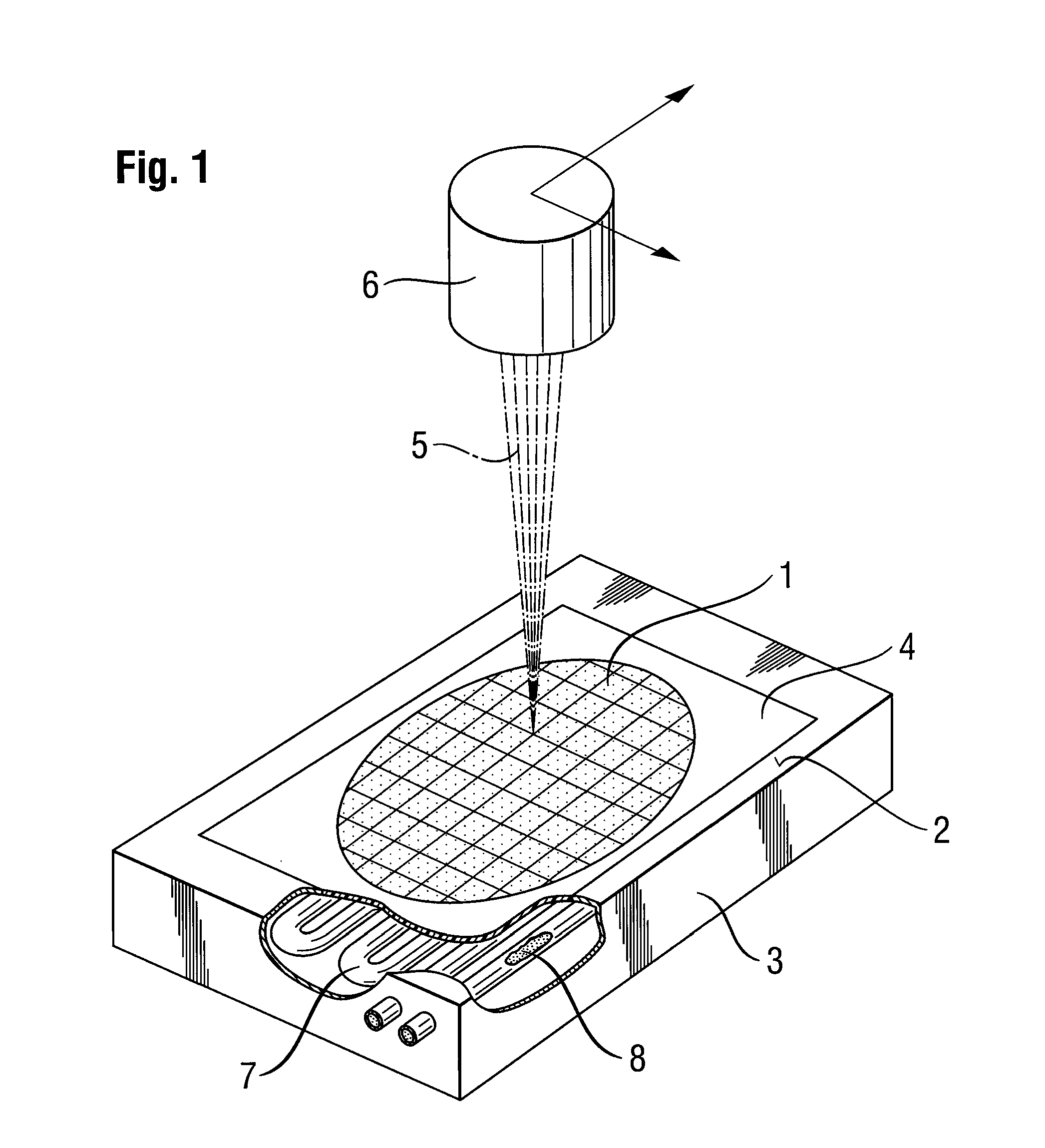
[0036]In a first embodiment example, a disk 1 which in this case is a sapphire wafer which is outfitted with components on one side and has a thickness of 90 μm and a diameter of 2″ is separated into individual parts (chips), e.g., with an edge length of 280 μm×280 μm. This means that the grid of planned severing lines has two groups of straight severing lines arranged in the trenches, as they are called, and extending at a distance of only 280 μm relative to one another, these groups being arranged so as to be rotated by 90° relative to one another.

[0037]Before the sapphire wafer 1 is placed on a supporting surface 2 of a workpiece holder 3, it is glued to a stretch foil 4 by its component side. The stretch foil 4 serves to hold together the chips that have been singularized after the severing process before they are spatially separated from one another by stretching the stretch foil 4 and subsequently removed.

[0038]After the stretch foil 4 which is glued to the sapphire wafer is p...


PUM

PropertyMeasurementUnit
thicknessaaaaaaaaaa
diameteraaaaaaaaaa
edge lengthaaaaaaaaaa

Abstract

The invention is directed to a method in which disks, particularly wafers, of brittle material are severed along planned severing lines by a laser by introducing thermal stresses. The temperature gradient required for this and the compressive stresses and tensile stresses resulting from it are generated in that the disk is first cooled proceeding from its underside at least along the planned severing lines toward the upper side of the disk, and the upper side of the disk is then acted upon by a laser beam along the planned severing lines. The description also relates to an apparatus for carrying out the method.

Description

CROSS-REFERENCE TO RELATED APPLICATION[0001]This application claims priority of German Application No. 10 2005 062 230.5, filed Dec. 21, 2005, the complete disclosure of which is hereby incorporated by reference.BACKGROUND OF THE INVENTION[0002]a) Field of the Invention[0003]The present invention relates to a method and apparatus for severing disks of brittle material, such as wafers.[0004]b) Description of the Related Art[0005]It is known to sever disks made of a brittle material such as glass, ceramic, silicon, quartz, gallium arsenide or sapphire by means of a laser through induced thermal stresses.[0006]For this purpose it is essential that the severing edge is formed exactly along the planned lines (referred to hereinafter as the precision of the severing line) and that the stress field caused by a sufficiently high temperature gradient is localized as precisely as possible on the planned severing edge.[0007]DE 693 04 194 T2 discloses a method of the type mentioned above in whi...

Claims


Application Information

Patent Timeline
Patent Type & Authority Patents(United States)
IPC IPC(8): B23K15/00
CPCC03B33/091B23K26/703B23K26/40B23K2203/50B23K2203/52B23K2103/50B23K2103/52H01L21/34H01L21/78
Inventor ZUEHLKE, HANS-ULRICHGRIEGER, JANEBERHARDT, GABRIELE
Owner 3D MICROMAC AG
Why Eureka
Try Eureka