Connector to be attached to liquid tank and liquid tank provided with the connector

a technology of liquid tank and connector, which is applied in the direction of liquid handling, couplings, packaging goods types, etc., can solve the problems of increasing the pressure inside the tank b>70/b>, t be used to realize a smooth circulation of liquid chemical, and the diameter of the container is small, so as to prevent the dust from entering the interior, prevent the improper connection, and reduce labor

Active Publication Date: 2010-10-26
SURPASS IND
View PDF18 Cites 18 Cited by
  • Summary
  • Abstract
  • Description
  • Claims
  • Application Information

AI Technical Summary

Benefits of technology

[0018]In the connector of the present invention, the plug and the socket each for the liquid passage connection and the plug and the socket each for the gas passage connection are integrated in a compact manner. Due to this, there is no need of connecting the plug with the socket in the side of the gas and no need of connecting the plug with the socket in the side of the liquid too. Only a singe connecting operation performed in the side of the liquid makes it possible to deliver the liquid. Consequently, it is possible to reduce labor in half. This makes the connector of the present invention advantageous in cost too. Further, in the conventional system described above, it is also possible to realize the circulation of the liquid of the tank even when the conventional system is still used in the side of the liquid, provided that the connector of the present invention is connected in the side of the gas (FIG. 10 described later) This is an advantageous effect obtained in the present invention.
[0019]Particularly, in the inventions described in claims 4 and 5, it is possible to prevent an improper connection between the plug and the socket from occurring, without fail. Further, in the invention described in claim 9, it is possible to obtain an effect in preventing the dust from entering the interior of the plug when a drum is transported. In the present inventions described in claim 10 and 11, it is possible to circulate the liquid of the tank and thereby allowing the liquid to be kept in purity and in concentration. This makes it possible to stabilize a process subsequent to such circulation of the liquid. This is another effect obtained in the present invention.

Problems solved by technology

Consequently, there is a fear that the pressure inside the tank 70 increases in use.
However, such gas plug is too small in diameter when used also in circulation of the liquid chemical, and therefore can't be used to realize a smooth circulation of the liquid chemical.

Method used


Image

  • Connector to be attached to liquid tank and liquid tank provided with the connector
  • Connector to be attached to liquid tank and liquid tank provided with the connector
  • Connector to be attached to liquid tank and liquid tank provided with the connector

Examples


Embodiment Construction

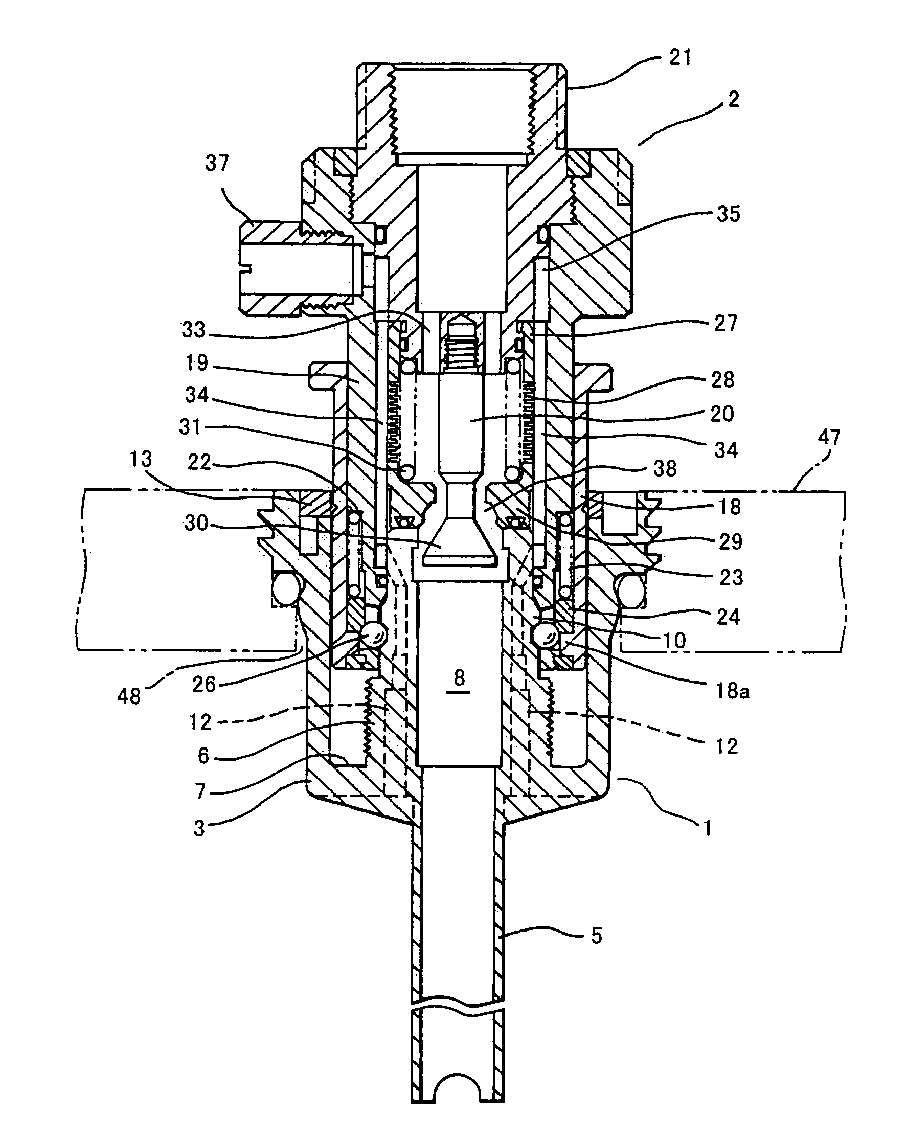
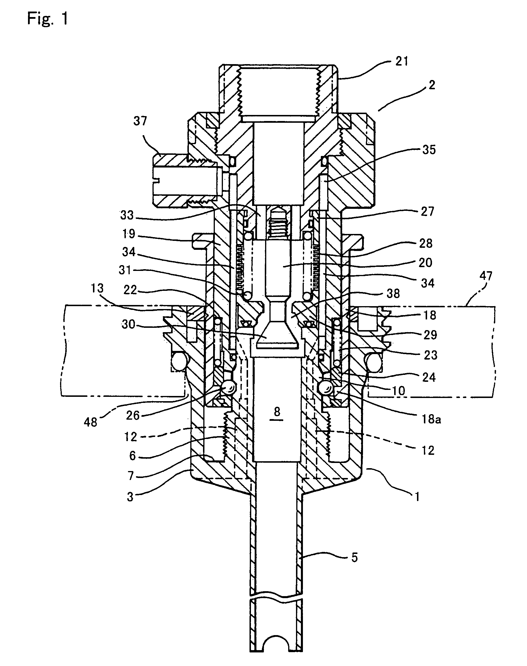
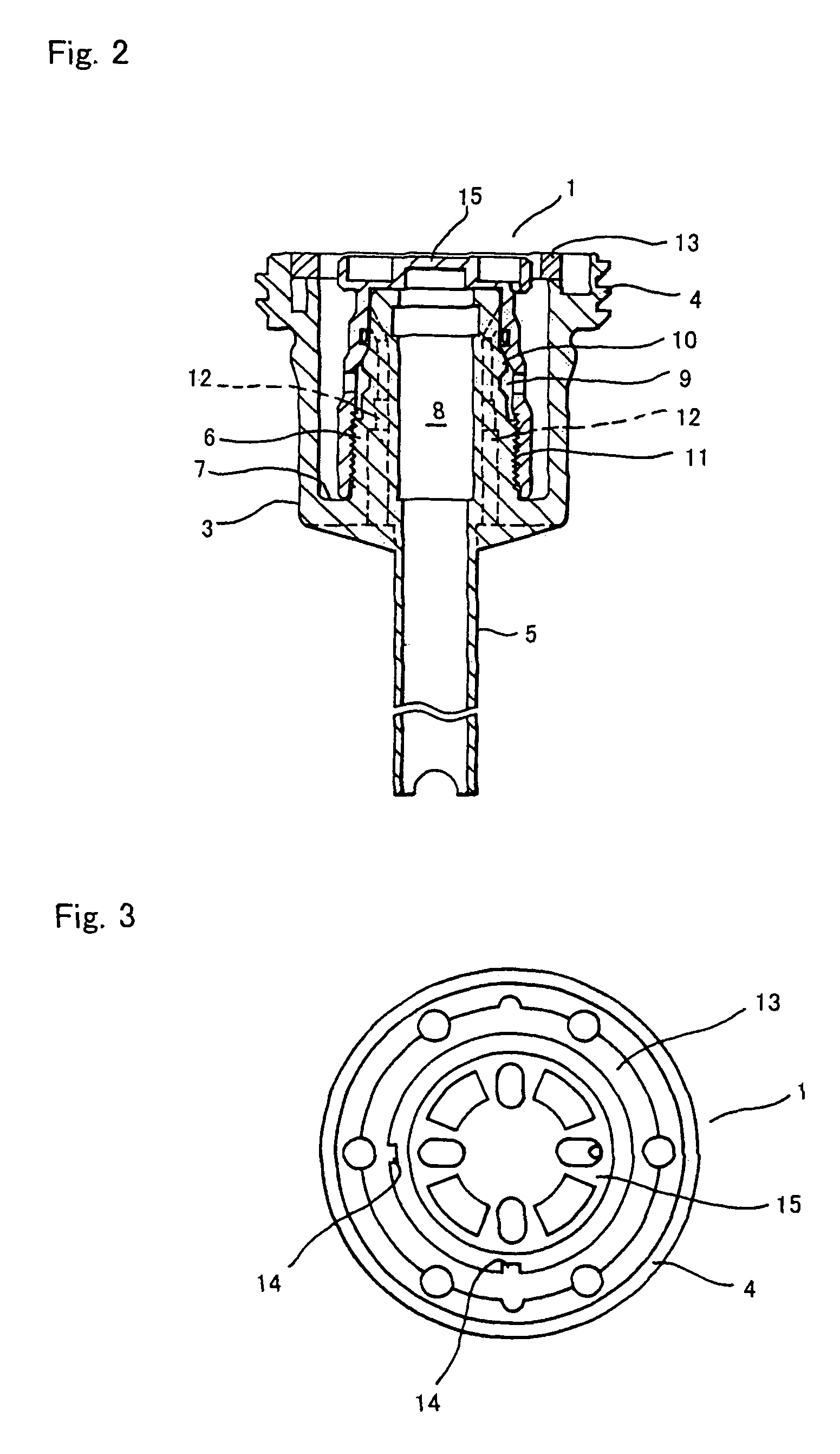
[0020]Preferred embodiments for carrying out the present invention will be described with reference to the accompanying drawings. FIG. 1 is a longitudinal sectional view illustrating in construction a connector constructed of both a plug 1 and a socket 2 each constructed according to the present invention. FIG. 2 is a longitudinal sectional view of the plug 1. FIG. 3 is a plan view of the plug 1. FIG. 4 is a longitudinal sectional view of the socket 2.

[0021]First, with reference to FIGS. 1 to 3, the plug 1 will be described in construction. The plug 1 is constructed of a cup-like body 3. A siphon tube 5 is integrally formed with the body 3. Alternatively, the siphon tube 5 may be independently formed and thereafter welded to the body 3. When the connector of the present invention is attached to the tank, the siphon tube 5 extends to the vicinity of the bottom of the tank.

[0022]Vertically provided in a central area of a concave portion 7 of the body 3 is a plug tube 6. The plug tube ...


PUM

PropertyMeasurementUnit
areaaaaaaaaaaa
timeaaaaaaaaaa
coloraaaaaaaaaa

Abstract

The object is to provide a connector to be attached to a liquid tank, which reduces a trouble of arranging a plug, is advantageous in cost and capable of preventing misconnection, is provided by compactly integrating two types of plugs, which are a liquid delivery plug and a gas feeding plug. The connector is to be attached to a liquid tank for delivery of an internal liquid, and is constructed of: a plug (1) fixedly mounted on the tank; and, a corresponding socket (2) connected thereto. The connector is characterized by the plug (1) and the socket (2), wherein: the plug (1) is provided with a liquid passage (8) and a gas passage (12); and, the socket (2) is provided with: a liquid passage (38) communicating with the liquid passage (8); a liquid passage connecting piece (21) communicating with the liquid passage (38); a gas passage (34) communicating with the gas passage (12); and, a gas passage connecting piece (37) communicating with the gas passage (34).

Description

TECHNICAL FIELD[0001]The present invention relates to a connector and a liquid tank provided with the connector to be attached to the tank, wherein: stored in the tank is a liquid such as semiconductor high-purity chemicals and ordinary chemicals; and, the connector is constructed of both a plug and a socket each used for delivery of the liquid.BACKGROUND ART[0002]In general, semiconductor high-purity chemicals and ordinary chemicals are stored in a tank good in resistance to these chemicals. As shown in FIG. 11, hitherto it has been known in the art that: formed in this tank 70 are two pieces of mouth stopper portions 71 and 71a; and, plugs 72 and 72a are mounted on these mouth stopper portions 71 and 71a, respectively, wherein each of the plugs 72 and 72a is provided with a plug portion not shown in the drawings. These plugs 72 and 72a function as lids for closing the mouth stopper portions 71 and 71a, respectively. Of these plugs 72 and 72a: one serves as a liquid passage connect...

Claims


Application Information

Patent Timeline
Patent Type & Authority Patents(United States)
IPC IPC(8): F16K51/00B67D1/04B67D1/08B67D7/02F16L37/38F16L41/08
CPCB67D1/0829B67D7/0266B67D7/0294B67D1/04F16L37/38F16L41/08
Inventor ABE, KOICHI
Owner SURPASS IND
Why Eureka
Try Eureka