
Common path systems and methods for frequency domain and time domain optical coherence tomography using non-specular reference reflection and a delivering device for optical radiation with a partially optically transparent non-specular reference reflector

a frequency domain and time domain optical coherence tomography technology, applied in the field of common path systems and methods for frequency domain and time domain optical coherence tomography using non-specular reference reflection and a delivering device for optical radiation with a partially optically transparent non-specular reference reflector, can solve the problems of serious frequency domain oct problems, the cost of telecentric optical systems is more expensive and difficult to assemble and align, and the implementation of critical dimensions of optical probes

Inactive Publication Date: 2010-10-26
IMALUX CORP
View PDF9 Cites 66 Cited by
  • Summary
  • Abstract
  • Description
  • Claims
  • Application Information

AI Technical Summary

Benefits of technology

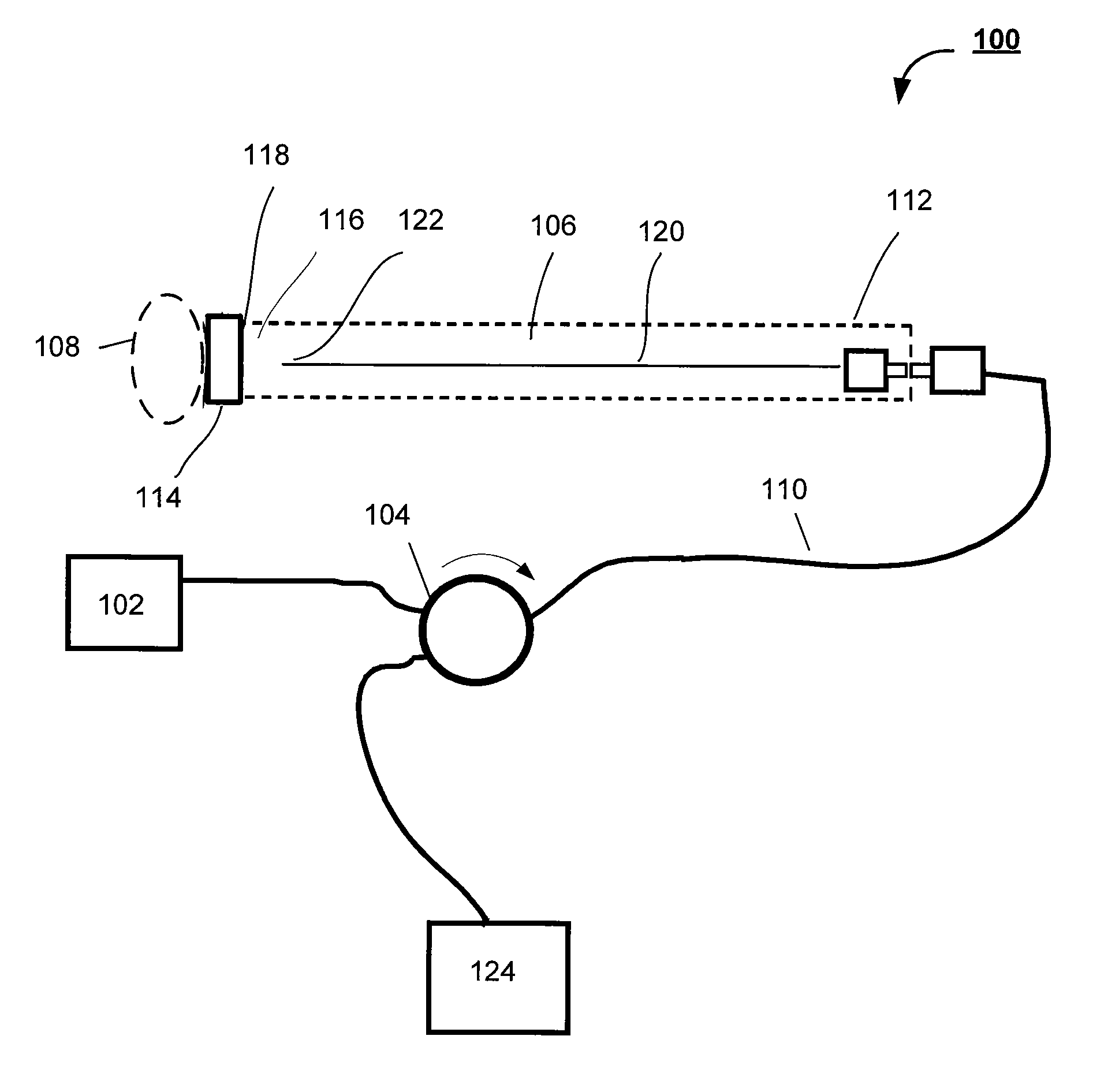
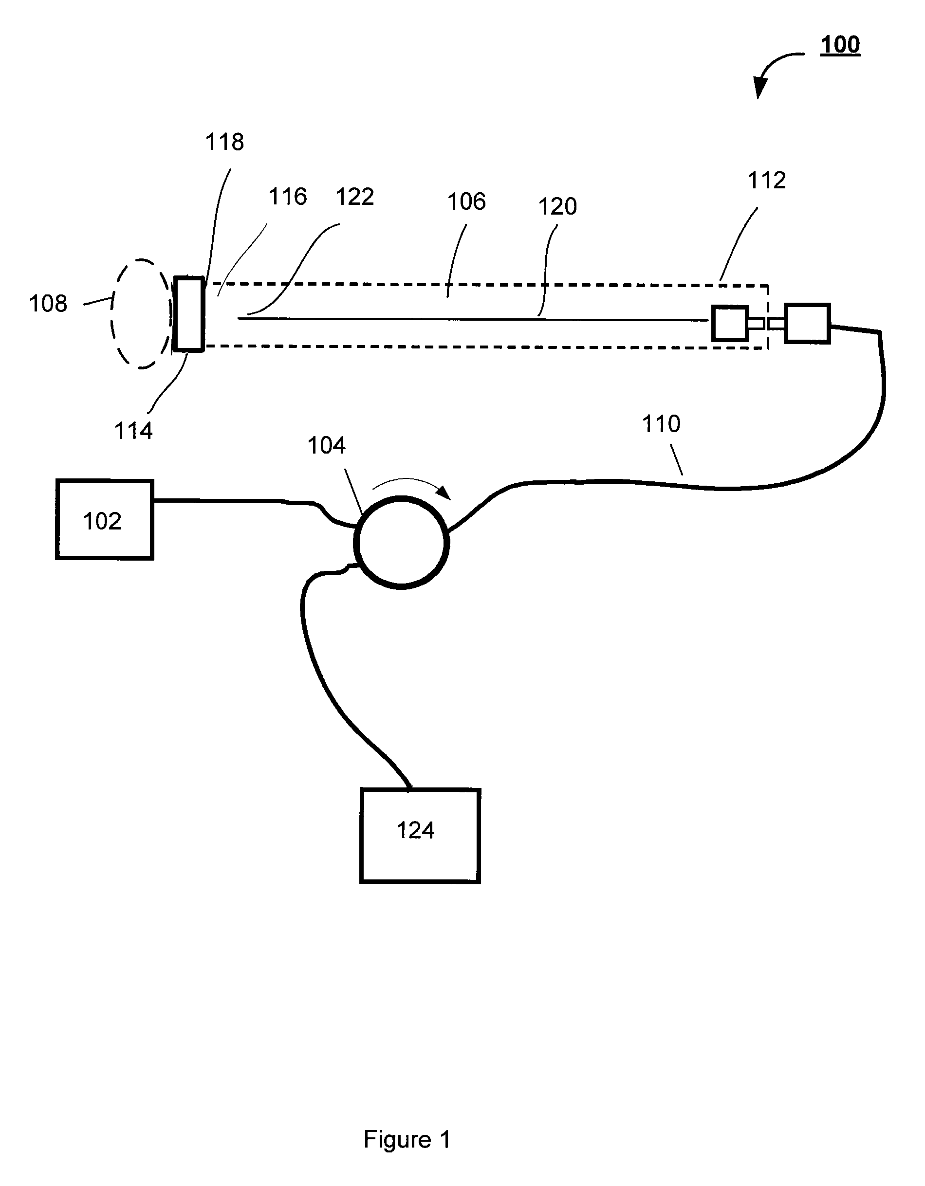
[0008]In accordance with the subject application, there are provided common path systems and methods for frequency domain and time domain optical coherence reflectometry / tomography that overcome the above mentioned problems and provide a stable power level of the non-specular reference reflection, which is used for producing a combination optical radiation representative of the optical radiation, reflected or backscattered from an associated sample.
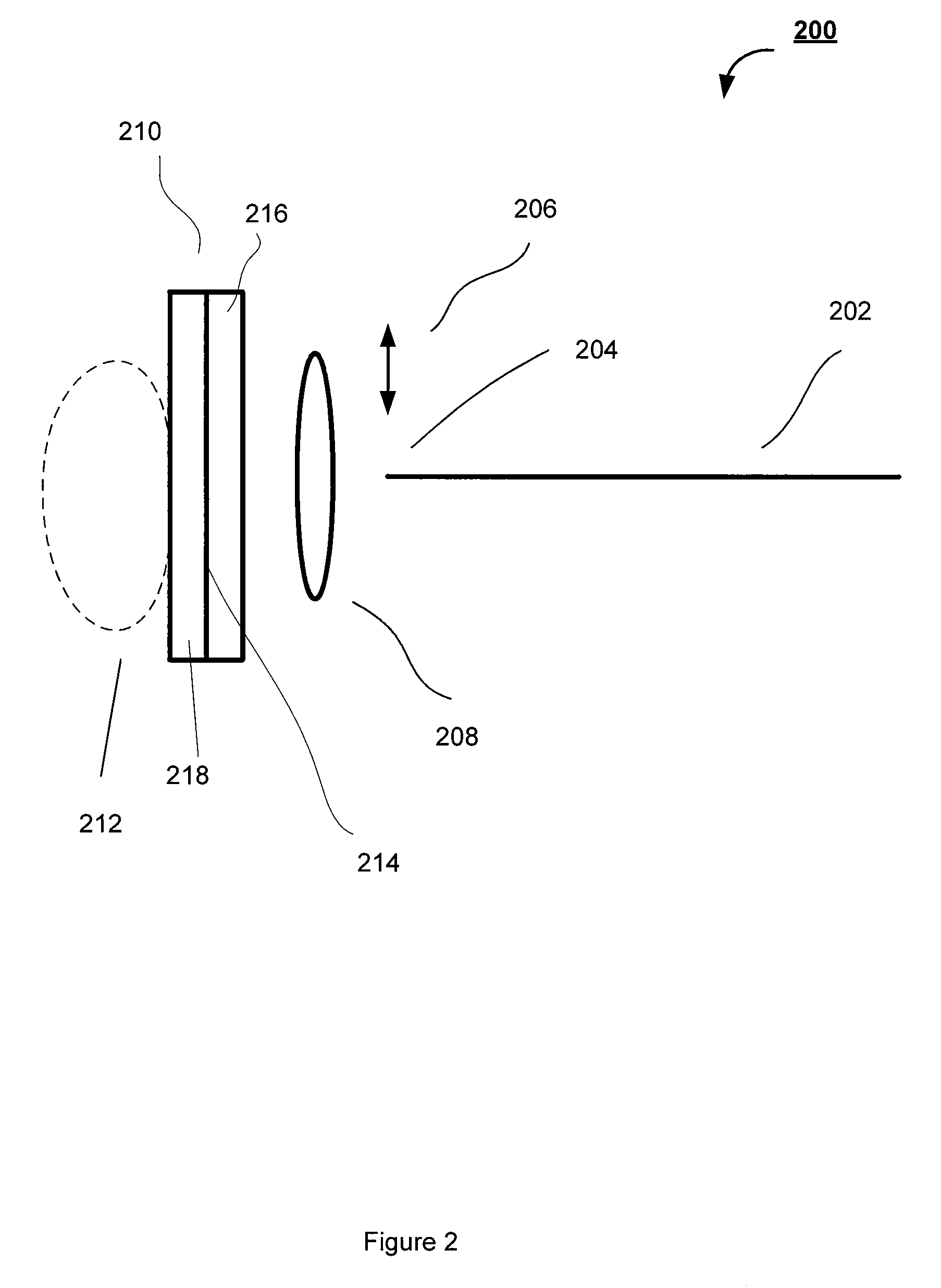
[0012]Still further in accordance with the subject application, there is provided a miniature optical fiber probe for use in common path time domain and frequency domain optical coherence tomography and reflectometry devices intended for biomedical applications that provides stable reference reflection using simple non-telecentric optics and a partially optically transparent non-specular reference reflector.

Problems solved by technology

Unfortunately, a telecentric optical system for the OCT optical probe requires substantially more space than a regular optical system, which makes it impractical for implementation in optical probes of critical dimensions, such as miniature endoscopic optical probes.
In addition, the telecentric optical system is more expensive and difficult to assemble and align.
As to the operation of common path OCT systems, using a reflection from a tip of the optical fiber as the reference portion, is known to work perfectly for time domain OCT, however it leads to serious problems for frequency domain OCT.
Therefore, direct spectral analysis of the optical radiation mix coming back from the optical probe and consisting of sample and reference portions of the optical radiation, axially separated by 20 mm or more, results in very high frequency fringes and requires excessive spectral resolution of the frequency domain OCT system and is an extreme burden for the data acquisition and signal processing system.
However, this solution for common path frequency domain OCT is prone to an additional noise originating from interference between two replicas of the reference radiation, which can make questionable a practical realization of the secondary interferometer layout.
However, using an angle cleaved tip of the optical fiber with high reproducibility of the cleave angle and reflection level, is technologically challenging.
Unfortunately, in a typical OCT probe optical system using non-telecentric optics, the beam incidence angle to the probe output window changes in the course of lateral scanning.
Thus, the requirements for good coupling of the optical radiation back to the optical fiber and maintaining the necessary coupling over the lateral scanning range are contradictory to each other.
Therefore, it could be very problematic or impossible to get a stable level of the reference reflection from a specular reflector located in the distal part of the optical fiber probe.

Method used


Image

  • Common path systems and methods for frequency domain and time domain optical coherence tomography using non-specular reference reflection and a delivering device for optical radiation with a partially optically transparent non-specular reference reflector
  • Common path systems and methods for frequency domain and time domain optical coherence tomography using non-specular reference reflection and a delivering device for optical radiation with a partially optically transparent non-specular reference reflector
  • Common path systems and methods for frequency domain and time domain optical coherence tomography using non-specular reference reflection and a delivering device for optical radiation with a partially optically transparent non-specular reference reflector

Examples


Embodiment Construction

[0028]The subject application is directed to systems and methods for visualizing subsurface regions of samples, and more specifically, to common path systems and methods for frequency domain and time domain optical coherence tomography (OCT) using a partially optically transparent non-specular reference reflector for providing internal depth profiles and depth resolved images of samples. The subject application is also directed and to a device for delivering optical radiation to an associated sample, preferably implemented as an optical fiber probe with a partially optically transparent non-specular reflector. The delivering device of the subject application is capable of being efficiently used in common path frequency domain and time domain reflectometry, as well. The common path frequency domain and time domain OCT devices are illustrated herein by means of examples of optical fiber devices, although it is evident that they may be implemented with the use of bulk optic elements. T...


PUM


Abstract

Provided are common path frequency domain and time domain OCT systems and methods that use non-specular reference reflection for obtaining internal depth profiles and depth resolved images of samples. Further provided is a delivering device for optical radiation, preferably implemented as an optical fiber probe with a partially optically transparent non-specular reflector placed in the vicinity of an associated sample. High frequency fringes are substantially reduced and a stable power level of the reference reflection is provided over the lateral scanning range. The partially optically transparent non-specular reflector is implemented as a coating placed on the interior surface of the optical probe window including spots of a metal, or a dielectric coating, separated by elements of another coating or just spaces of a clean substrate. In an alternative embodiment, the scattering elements are made 3-dimensional, having, for example, a spherical shape.

Description

CROSS-REFERENCE TO RELATED APPLICATIONS[0001]This application is based on and claims priority to U.S. Provisional Patent Application Ser. No. 60 / 824,713, filed on Sep. 6, 2006, the entirety of which is incorporated herein.BACKGROUND OF THE INVENTION[0002]The subject application relates generally to systems and methods for visualizing subsurface regions of samples. In particular, the subject application is directed to common path systems and methods for frequency domain and time domain optical coherence tomography using non-specular reference reflection for providing internal depth profiles and depth resolved images of samples. The subject application is also directed to a delivering device for optical radiation, preferably implemented as an optical fiber probe with a partially optically transparent non-specular reflector to be used in common path frequency domain and time domain optical coherence tomography and reflectometry devices.[0003]As known in the art, optical coherence refle...

Claims


Application Information

Patent Timeline
Patent Type & Authority Patents(United States)
IPC IPC(8): G01B9/02
CPCG01N21/4795
Inventor AMAZEEN, PAUL G.FELDCHTEIN, FELIX I.
Owner IMALUX CORP
Learn More