
Light pulse positioning with dispersion compensation

a technology of dispersion compensation and light pulse positioning, applied in the direction of optics, instruments, prisms, etc., can solve the problems of slow scanning speed, inability or difficulty to position the laser beam non-sequentially or randomly, and the speed enabled by the galvanometer-driven mirror is typically only about several frames per second, so as to improve the efficiency of multi-photon excitation, high refreshing rate scanning, and the effect of increasing resolution

Inactive Publication Date: 2010-10-26
ZENG SHAOQUN +3
View PDF7 Cites 5 Cited by
  • Summary
  • Abstract
  • Description
  • Claims
  • Application Information

AI Technical Summary

Benefits of technology

"The present invention improves the existing light pulse positioning systems by providing both spatial and temporal dispersion compensation using a single dispersive element such as a prism. The acousto-optical device includes a first acousto-optical deflector and a second acousto-optical deflector for positioning the light pulse in two directions. The prism is placed in front of the acousto-optical device and is oriented to compensate for the spatial and temporal dispersion caused by the acousto-optical device. The invention allows for optimal spatial and temporal dispersion compensation by the prism, resulting in improved accuracy of positioning the light pulse."

Problems solved by technology

Galvanometer-driven mirror, although still widely used in laser scanning devices, has its limitations, among which are slow scanning speed and inability or difficulty to position the laser beam non-sequentially or randomly.
The scanning speed enabled by a galvanometer-driven mirror is typically only about several frames per second, too slow to image the fast response of biological samples.
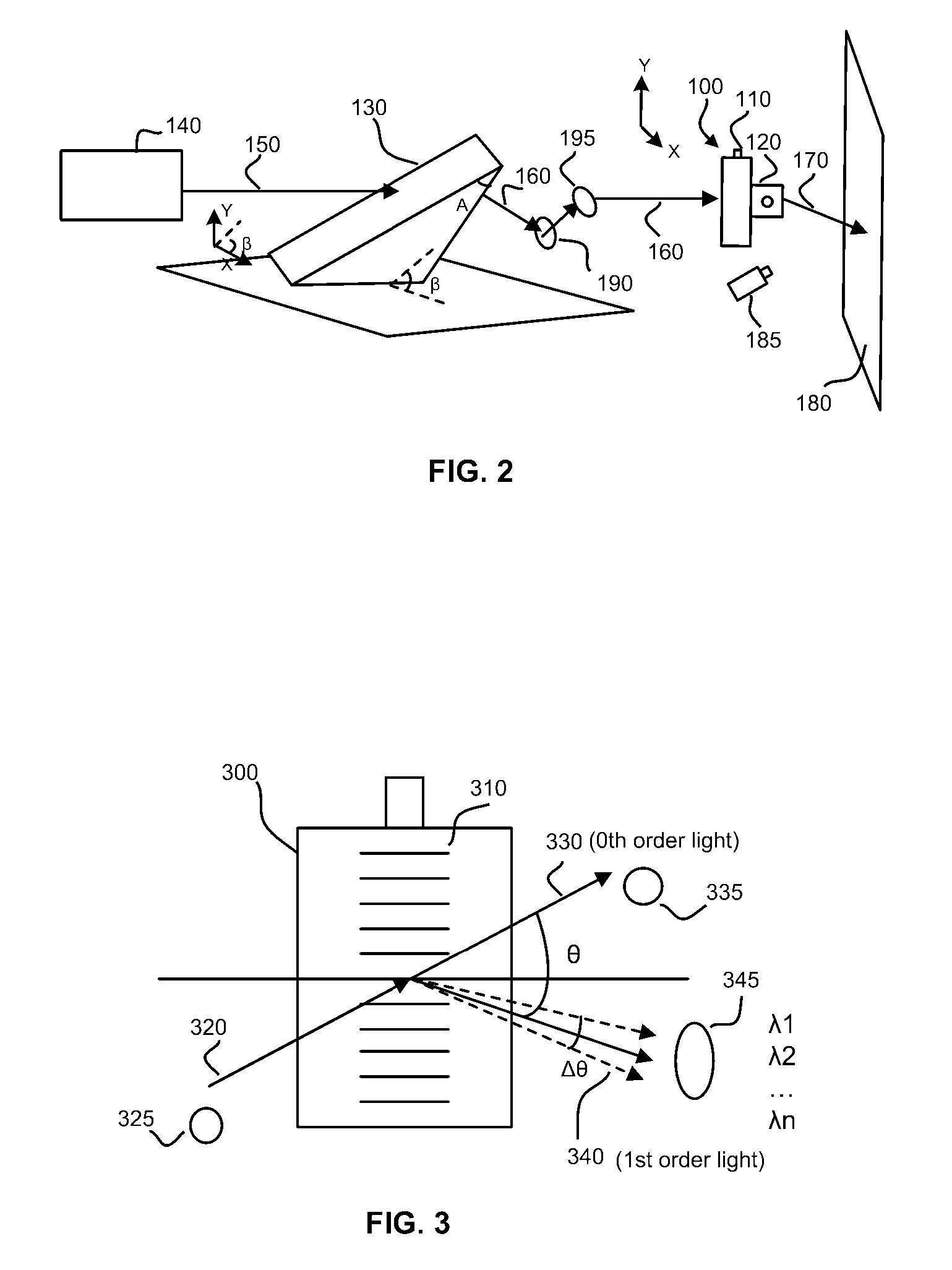
One significant technical issue of using AOD as a scanner or positioner is that AOD is highly dispersive.
The dispersion caused by AOD limits its applications.
Temporal dispersion of laser pulses causes additional problems.
For example, in multi-photon microscopy, dispersion can significantly degrade the efficiency and quality of multi-photon excitation which is the basis for this type of microscopy.
The design in this patent does not address temporal dispersion.

Method used


Image

  • Light pulse positioning with dispersion compensation
  • Light pulse positioning with dispersion compensation
  • Light pulse positioning with dispersion compensation

Examples


Embodiment Construction

[0038]Disclosed below are representative embodiments of the systems and methods in accordance with the present inventions. The representative embodiments are disclosed herein for purposes of illustrating. The disclosed systems and methods should not be construed as limiting in any way. Instead, the present disclosure is directed toward all novel and nonobvious features and aspects of the various disclosed embodiments, alone and in various combinations and subcombinations with one another. Therefore, these and other variations upon the specific embodiments are intended to be covered by the present inventions. The systems and methods are not limited to any specific aspect or feature or combinations thereof, nor to the disclosed systems and methods require that any one or more specific advantages be present or problems be solved.

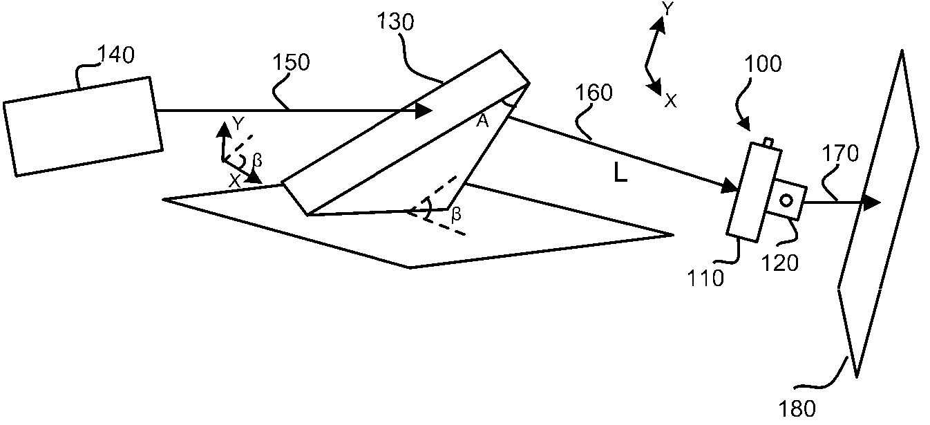
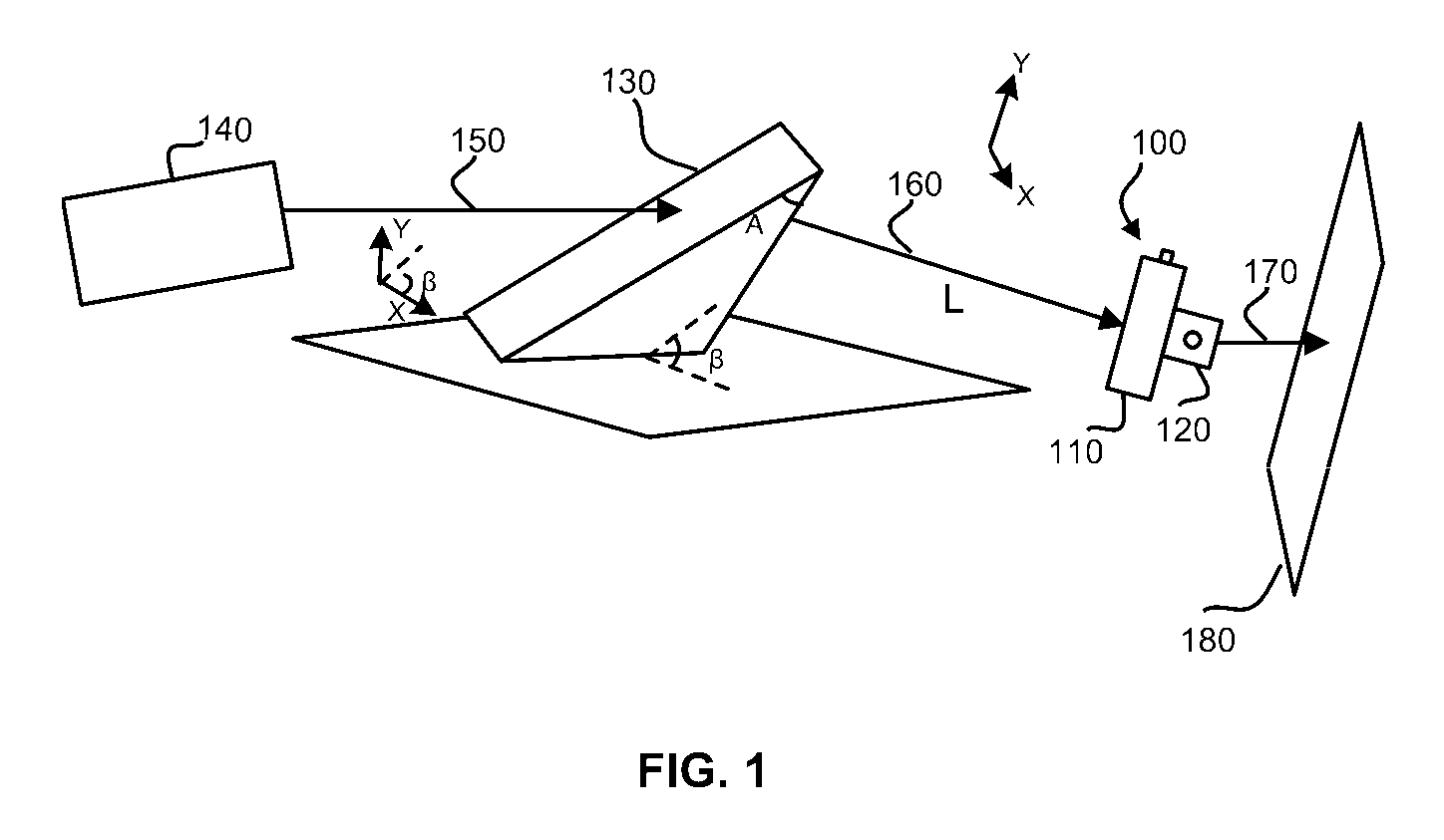
[0039]FIG. 1 is a schematic diagram of an embodiment of a two-dimensional scanning / positioning apparatus having simultaneous spatial dispersion compensation an...


PUM

PropertyMeasurementUnit
tilt angleaaaaaaaaaa
acoustic velocityaaaaaaaaaa

Abstract

A light pulse positioning apparatus with dispersion compensation includes an acousto-optical device and a dispersive element optically coupled thereto. The dispersive element is placed and oriented in relation to the acousto-optical device to spatially and temporally disperse the light pulse and thus compensate, respectively, a spatial dispersion and a temporal dispersion caused by the acousto-optical device. The acousto-optical device can include one or more acousto-optical deflectors for one-dimensional or two-dimensional laser pulse positioning. The dispersive element can be a prism placed in front of the acousto-optical device. In a two-dimensional configuration, a single prism, if properly oriented, is sufficient for dispersion compensation of both acousto-optical deflectors.

Description

CROSS-REFERENCE TO RELATED APPLICATIONS[0001]This application claims benefit of an earlier filing date of Chinese patent application, Serial No. 200510019130.0, filed Jul. 20, 2005, entitled “Laser Beam Scanning Apparatus Based on Two-Dimensional Acousto-Optical Deflectors”.BACKGROUND[0002]1. Field of the Invention[0003]The present invention relates generally to systems and methods for light pulse positioning or steering, and particularly to systems and methods for laser beam scanning using acousto-optical deflectors (AOD). The invention has applications in various fields including laser imaging such as multi-photon laser scanning microscopy, laser micromanipulation such as laser micromachining and laser ablation, and optical storage such as CD writing and / or reading.[0004]2. Description of the Prior Art[0005]Laser has been used for microimaging, micromanipulation and optical data systems in a variety of ways. Laser microimaging found in modern optical instruments is playing an incr...

Claims


Application Information

Patent Timeline
Patent Type & Authority Patents(United States)
IPC IPC(8): G02F1/11G02B26/08G02F1/29G02F1/01G02B26/00
CPCG02B5/04G02F1/33
Inventor ZENG, SHAOQUNLUO, QINGMINGZHAN, CHENLV, XIAOHUA
Owner ZENG SHAOQUN
Learn More