
Robot for computed tomography interventions

a computed tomography and robot technology, applied in the field of robots for computed tomography interventions, can solve the problems of reducing the surgeon's visual ability, limiting the modality, and the relative high and limiting the radiation exposure of the patient and the physician

Active Publication Date: 2010-10-26
THE JOHN HOPKINS UNIV SCHOOL OF MEDICINE
View PDF51 Cites 27 Cited by
  • Summary
  • Abstract
  • Description
  • Claims
  • Application Information

AI Technical Summary

Benefits of technology

The patent describes a system and method for accurately positioning a medical instrument or device in a patient's body for computed tomography (CT) guided operations. The system includes a robot and a control device that work together to position the instrument in a desired orientation and insert it through a predetermined point in the patient's body. The technical effects of this system include improved accuracy and efficiency in positioning the instrument, reduced risk of complications, and improved outcomes for patients.

Problems solved by technology

One of the main problems encountered in minimally invasive procedures is, in contrast to open surgical procedures, a dramatic reduction in the surgeon's visual ability.
The major limitations of CTF interventions are the relatively high radiation exposure [Gianfelice D, Lepanto L, Perreault P, Chartrand-Lefebvre C; Milette P C: Effect of the learning process on procedure times and radiation exposure for ct fluoroscopy-guided percutaneous biopsy procedures.
However, the major limitation to the modality is the relatively high radiation exposure to patient and physician [Nawfel R D, Judy P F, Silverman S G, Hooton S, Tuncali K, Adams D F. Patient and personnel exposure during ct fluoroscopy-guided interventional procedures.
The major limitation of CTF is the relatively high radiation exposure to patient and physician.
This approach, however, requires specialized robotic hardware, image registration, and guidance algorithms.

Method used


Image

  • Robot for computed tomography interventions
  • Robot for computed tomography interventions
  • Robot for computed tomography interventions

Examples


Embodiment Construction

Description of the Robot

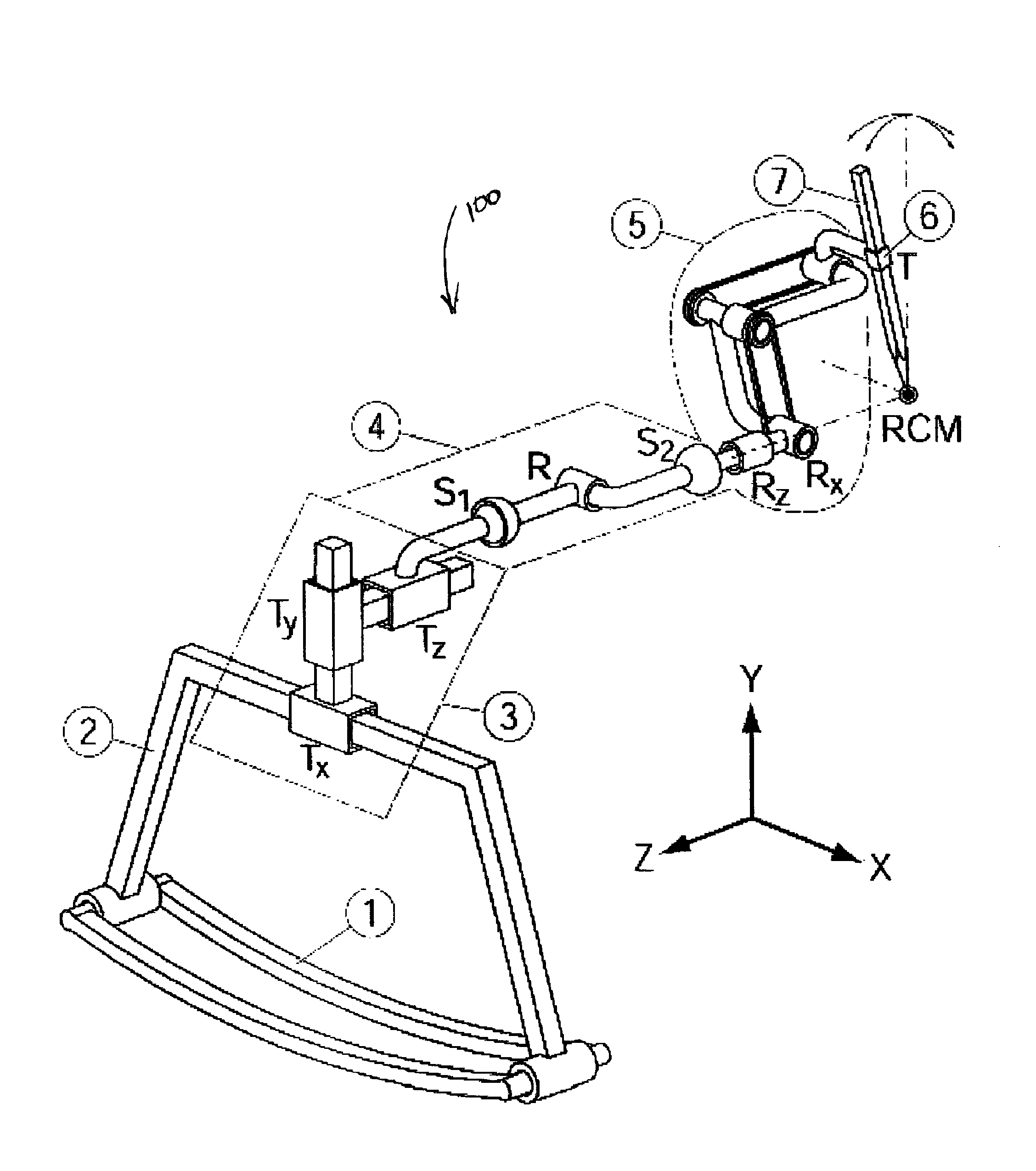
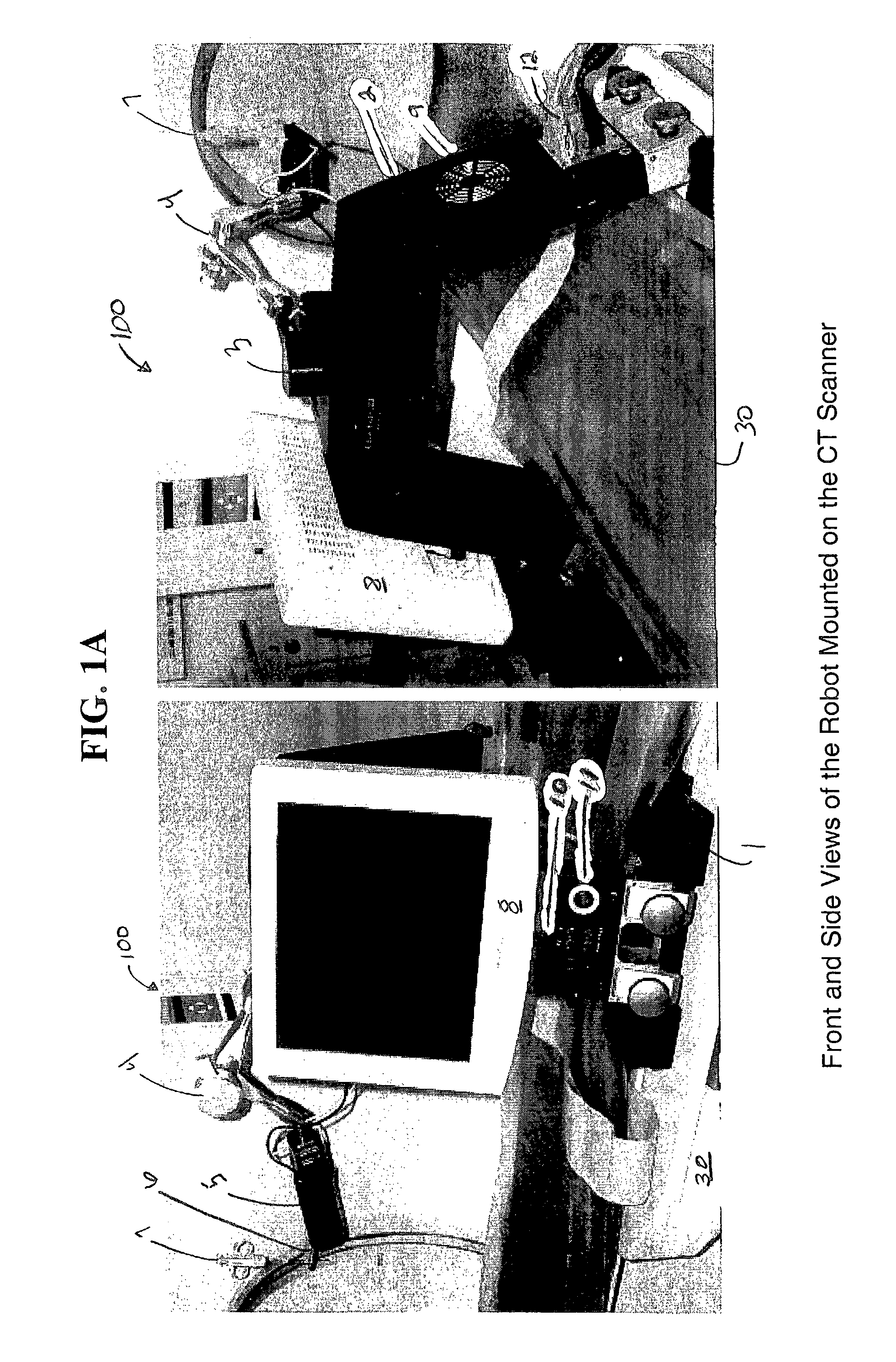
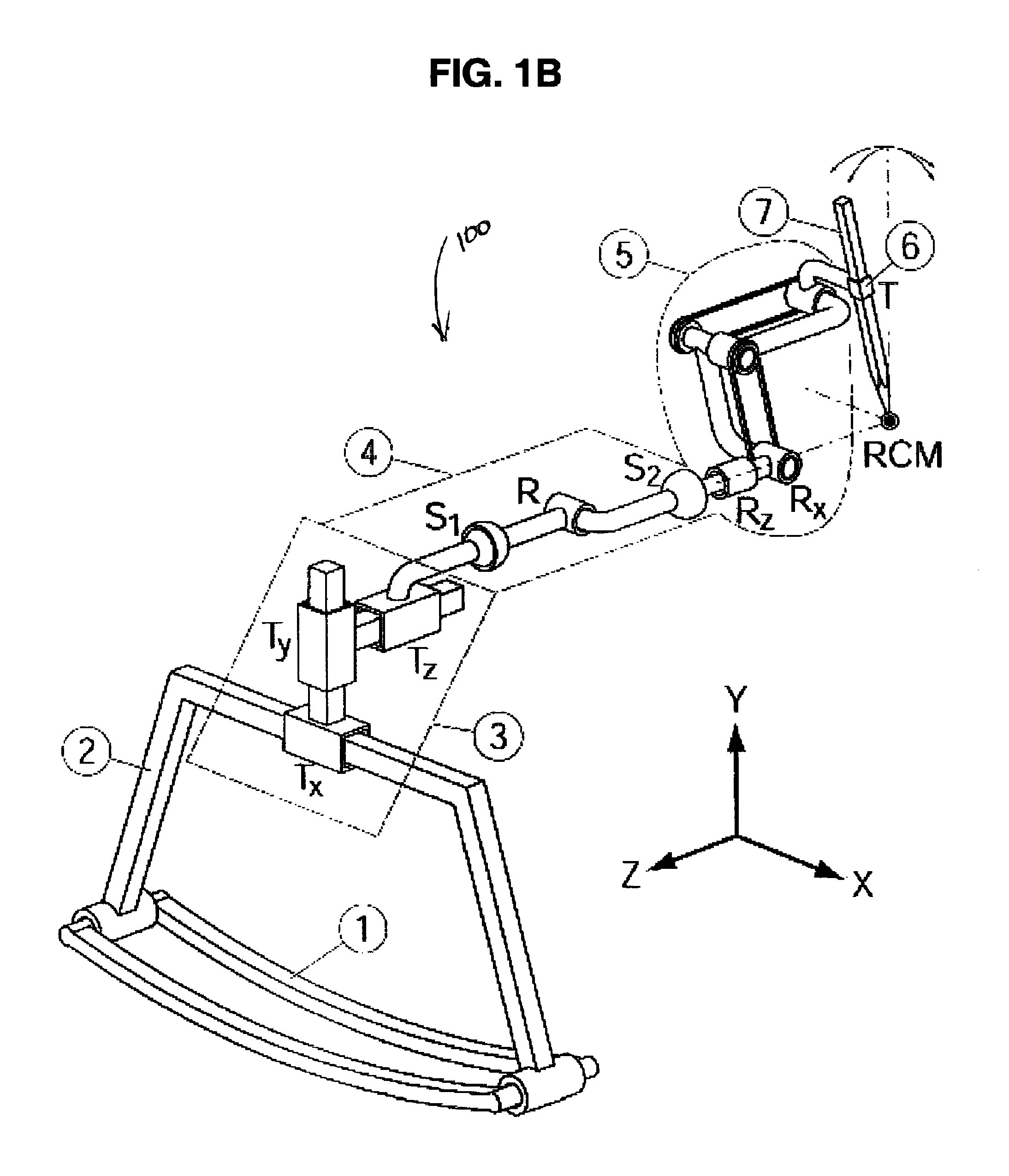
[0040]The preferred embodiment of the present invention uses PAKY and RCM robotic modules assembled in a CT-specific configuration and will undergo clinical trials at Georgetown University Medical Center [Cleary K, Stoianovici D, Watson V, Cody R, Hum B, and Lindisch D: “Robotics for pereutaneous spinal procedures: initial report,” Computer Assisted Radiology and Surgery (CARS) 2000, Elsevier, 128-33]. One component of the preferred system is the PAKY-RCM robot developed at the URobotics Laboratory at Johns Hopkins. This robot includes the PAKY needle driver (Percutaneous Access of the Kidney) and the RCM (Remote Center of Motion) robot [Stoianovici, D., Witcomb, L. L., Anderson, J. H., Taylor, R. H., Kavoussi, L. R.: “A Modular Surgical Robotic System for Image Guided Percutaneous Procedures”, 1998 MICCAI, Lecture Notes in Computer Science, Springer-Verlag, Vol. 1496, pp. 404-410, 1998].

[0041]FIGS. 1A and 1B illustrate the current preferred embodiment of the...


PUM


Abstract

A system and method for CT guided instrument targeting including a radiolucent instrument driver; a robot and a control box. The robot includes a robotic module that positions the radiolucent driver about two directions coincident a predetermined point. The control device is connected to the robot and the radiolucent instrument driver. The control driver sends a robot control signal to the robot that causes the robotic module to place the radiolucent instrument driver in a desired orientation with respect to the predetermined point. After the radiolucent instrument driver is in the desired orientation, the control device sends a driver control signal to the radiolucent instrument driver that causes the radiolucent driver to insert a medical instrument or device through the predetermined point to a location proximate a target point in a patient.

Description

CROSS REFERENCE TO RELATED APPLICATION[0001]This application claims priority to Provisional Patent Application No. 60 / 375,559, entitled TRACKER ROBOT FOR CT-GUIDED INTERVENTIONS, filed on Apr. 25, 2002, the contents of which are incorporated herein by reference.STATEMENT REGARDING FEDERALLY SPONSORED RESEARCH[0002]This work was partially supported by grant No. DAMD17-99-1-9022 from the U.S. Army Medical Research Acquisition Activity (USAMRAA) and by grant No 1R21CA088232-01A1 from the National Cancer Institute (NCI). This work was also supported in part by the National Science Foundation under Cooperative Agreement EEC 9731478, “Engineering Research Center for Computer-Integrated Surgical Systems and Technology.”BACKGROUND OF THE INVENTION[0003]1. Field of the Invention[0004]The present invention relates to robotic devices and methods for instrument targeting. In particular, the invention relates to systems and methods for computer assisted image-based instrument targeting used in c...

Claims


Application Information

Patent Timeline
Patent Type & Authority Patents(United States)
IPC IPC(8): A61B5/05A61B19/00
CPCA61B19/22A61B19/2203A61B19/201Y10T74/20207A61B2019/265A61B2019/5229A61B2017/3409A61B2090/506A61B34/70A61B34/30A61B90/11A61B2090/372
Inventor STOIANOVICI, DANMAZILU, DUMITRUKAVOUSSI, LOUIS R.
Owner THE JOHN HOPKINS UNIV SCHOOL OF MEDICINE
Learn More