
Live fire burn room and insulating system for a live fire burn room

a technology of insulating system and burn room, which is applied in the field of live fire burn room and insulating system, can solve the problems of material damage, loss of inherent moisture, and continued deterioration

Active Publication Date: 2010-11-02
FIRE FACILITIES
View PDF17 Cites 15 Cited by
  • Summary
  • Abstract
  • Description
  • Claims
  • Application Information

AI Technical Summary

Benefits of technology

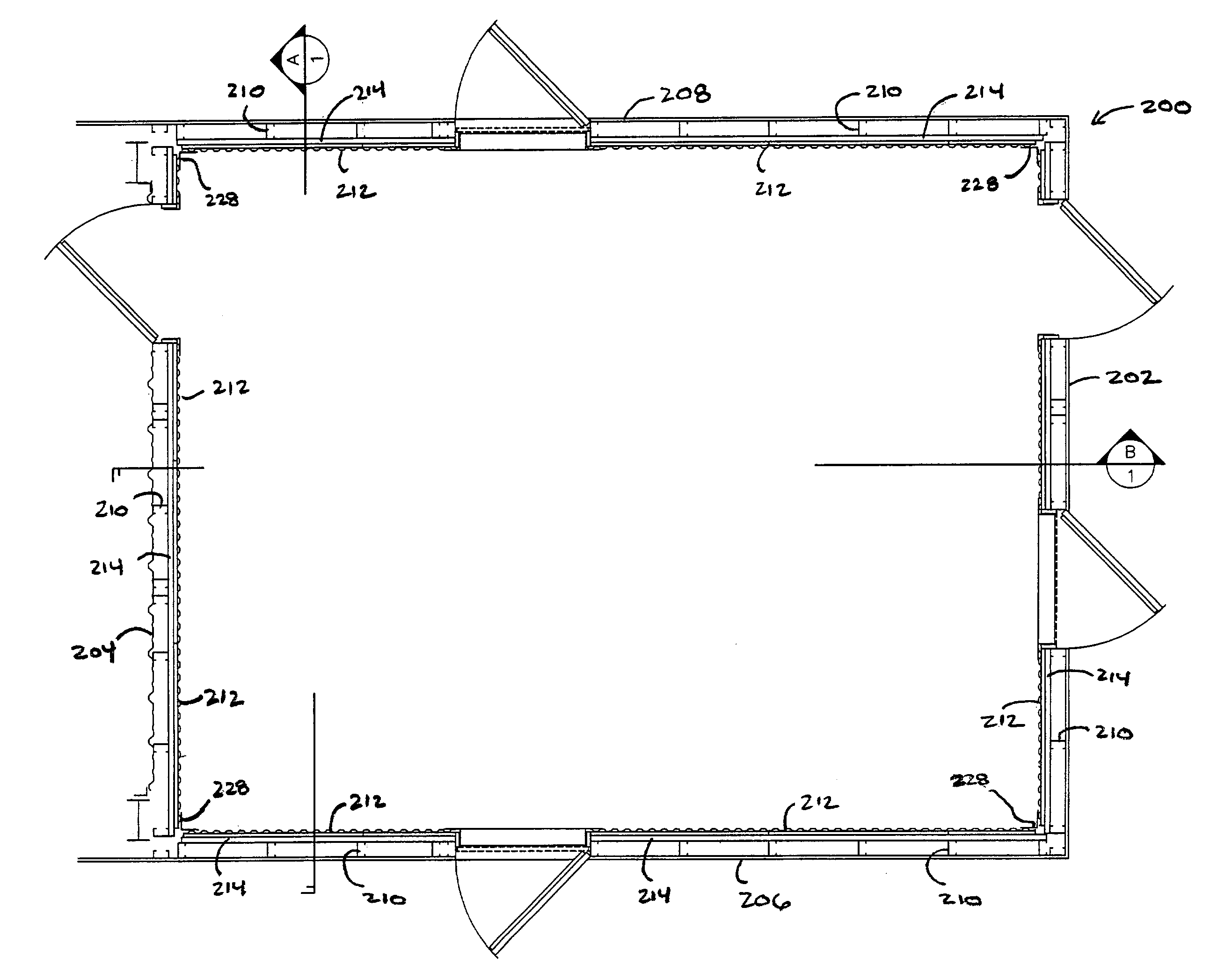
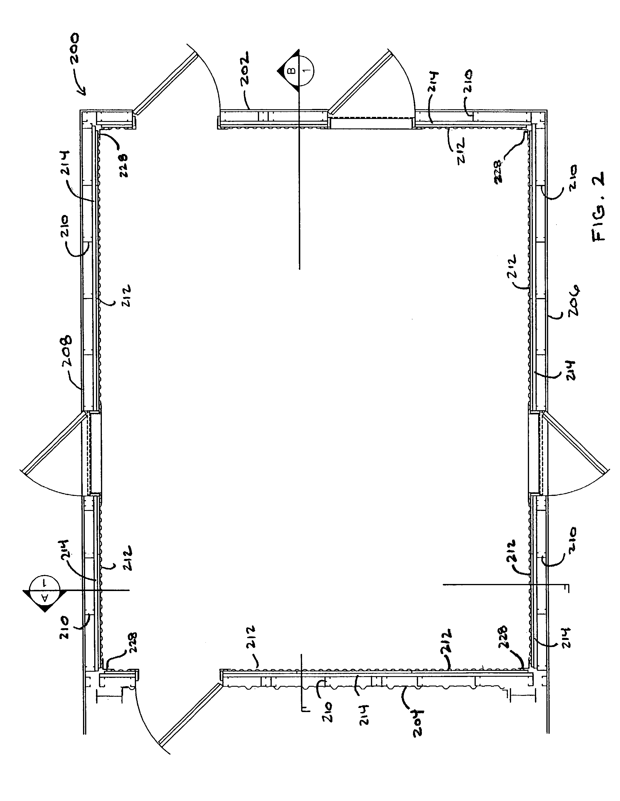
[0020]The first wall face panel is a stainless steel panel, a floating wall face panel or a corrugated face panel in alternative embodiments. The first wall includes a plurality of wall studs in one embodiment and is a concrete wall in another embodiment. The first wall face panel is attached to the first wall in a manner that allows the first wall face panel to move in response to temperature changes inside of the burn room in one other embodiment.
[0030]The second wall face panel and the first wall face panel are configured inside of the burn room to move independently of each other as the temperature inside of the burn room changes in one embodiment. The second wall face panel and the ceiling face panel are configured inside of the burn room to move independently of each other as the temperature inside of the burn room changes in another embodiment. The first wall face panel is attached to the ceiling face panel in a manner that allows the first wall face panel and the ceiling face panel to each move as the temperature inside of the burn room changes in yet another embodiment.
[0036]In one embodiment, the first face panel and the second face panel are configured to move independently of each other as the temperature inside of the burn room increases and decreases. The insulating system is configured such that the first face panel is disposed for attachment to the wall of the burn room and the second face panel is disposed for attachment to the ceiling of the burn room in another embodiment and is configured such that the first face panel is not physically attached to the second face panel other than indirectly through the burn room when the insulating system is installed in the burn room in one other embodiment. The first face panel is attached to the second face panel in a manner that allows the first face panel and the second face panel to each move as the temperature inside of the burn room changes in another embodiment.
[0039]The second face panel and the first face panel are configured to move independently of each other as the temperature inside of the burn room changes in one embodiment and the second face panel and the third face panel are configured to move independently of each other as the temperature inside of the burn room changes in another embodiment. The first face panel is attached to the third face panel in a manner that allows the first face panel and the third face panel to each move as the temperature inside of the burn room changes in still another embodiment.

Problems solved by technology

These materials are susceptible to damage from high heat and high temperatures.
When concrete is heated to a surface temperature of 650 degrees Fahrenheit, for example, it begins to lose its inherent moisture and at 750 to 850 degrees, the surface begins to powder leading to continued deterioration.
Hot rolled steel will distort at 1000 degrees Fahrenheit and cold rolled steel can fail at temperatures as low as 800 degrees Fahrenheit.
The problem with refractory concrete or refractory tiles is that these materials do not provide good insulation.
In addition, refractory concrete and tiles are subject to damage from impact with foreign objects and these materials are expensive to replace.
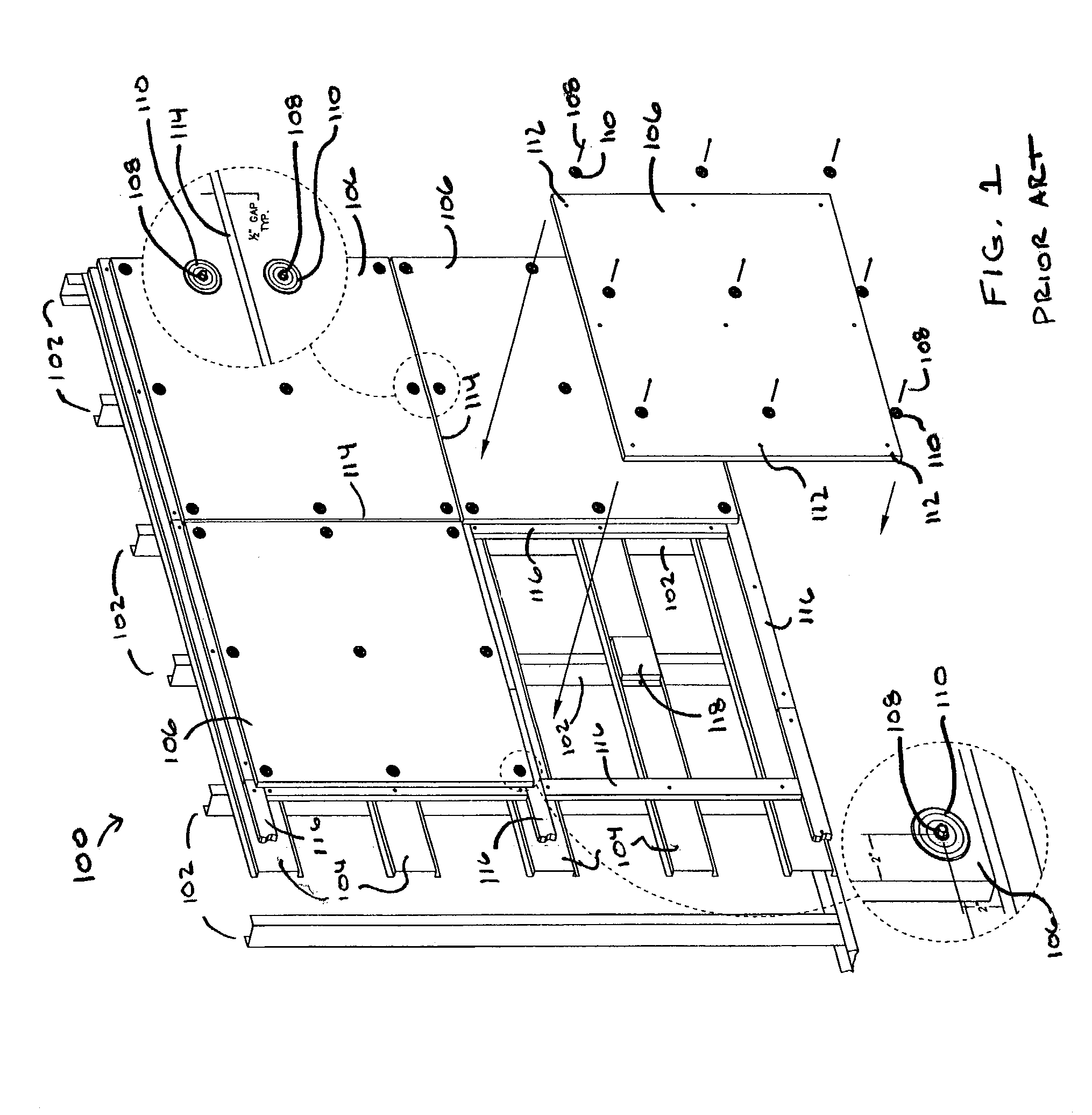
Although the prior art insulating system shown in FIG. 1 generally provides for adequate insulation to protect the structural framework and components of the burn room and training structure, it too suffers from several drawbacks.
To begin with, the individual insulating panels 106 are expensive to replace.
This is important because, in general, they have a limited useful life after which time they must be replaced.
The panels are also susceptible to damage from impacts with foreign objects and to premature spalling and / or cracking that can result from various environmental conditions present in the burn room during firefighter training exercises (e.g., various heat / moisture conditions).
Damaged panels as well as panels that show signs of significant cracking and / or spalling may also require replacement.
Proper installation of insulating panels 106 is also difficult to achieve.
This is because as the panels heat up, they have a tendency to move and slip due to warpage and expansion.
If mounting screws 108 are over tightened, the insulating panels will crack at the location of the mounting screws because they will not have the ability to expand and move properly at those locations.
To further complicate matters, the greater the rise in temperature, the greater the expansion and warpage that results.
What may be an adequate adjustment of mounting screws 108 at one temperature may not allow for adequate expansion and movement of the insulating panels at a higher temperature.
Furthermore, if the screws are left too loose, the panels will not be properly secured to the walls when the burn room is at lower temperatures such as normal room temperature.
Excessive warranty costs can be incurred to replace insulating panels that are damaged as a result of improper installation.
Another problem with the prior art insulating system of FIG. 1 is that the insulating system does not provide a complete thermal block between the inside of the burn room and the metal structural framework of the burn room.

Method used


Image

  • Live fire burn room and insulating system for a live fire burn room
  • Live fire burn room and insulating system for a live fire burn room
  • Live fire burn room and insulating system for a live fire burn room

Examples


Embodiment Construction

[0065]While the present invention will be illustrated with reference to a particular live fire burn room and a particular insulating system having particular configurations and particular features, the present invention is not limited to these configurations or to these features and other configurations and other features can be used. Also, although the present invention will be illustrated with reference to using the burn room and insulating system in connection with firefighter training structures, the present invention may have use in other applications and other industries as well. For example, the insulation system of the present invention may be used to insulate rooms other than burn rooms.

[0066]Generally, the present invention involves a live fire burn room and an insulating system for a live fire burn room. The term burn room, or live fire burn room, as used herein, means a room that is specially designed to contain a continuous live training fire during a firefighter traini...


PUM


Abstract

A live fire burn room and an insulating system for a live fire burn room are disclosed. The burn room includes a structural framework. The insulating system includes a face panel, at least one face panel mounting bracket for attaching the face panel to the structural framework of the burn room, and an insulating layer disposed between the face panel and the structural framework of the burn room.

Description

FIELD OF THE INVENTION[0001]The present invention relates generally to a firefighter training apparatus and system. More specifically, it relates to a live fire burn room and an insulating system for a live fire burn room that can be incorporated into firefighter training structures and towers.BACKGROUND OF THE INVENTION[0002]Live firefighter training exercises typically involve the use of a training tower or other training structure specially designed for the purpose of training firefighters. These structures generally include two or more rooms. Simple training structures, for example, may have only two rooms. One of the rooms is typically designed to accommodate the fire used in live firefighter training. The other room is provided for the purpose of allowing firefighters to enter the structure to put out the live training fire. Other more sophisticated training structures may have several rooms and several floors, including two or more rooms that are specially designed to contain...

Claims


Application Information

Patent Timeline
Patent Type & Authority Patents(United States)
IPC IPC(8): E04B1/343A62C99/00E04B1/94
CPCA62C99/0081E04B1/94
Inventor WESTRA, STEVEN P.
Owner FIRE FACILITIES
Learn More