Variable resonator

a variable resonator and resonator technology, applied in the field of line-type variable resonators, can solve the problems of loss increase and loss of variable resonators, and achieve the effects of low loss, wide frequency variation range, and reduced resistance of the switch

Inactive Publication Date: 2010-11-02
NTT DOCOMO INC
View PDF17 Cites 7 Cited by
  • Summary
  • Abstract
  • Description
  • Claims
  • Application Information

AI Technical Summary

Benefits of technology

[0014]As described above, according to the present invention, the first resonator and the second resonator are connected in parallel to the input / output line. When the terminal switch is turned off, resonance occurs at a frequency at which the sum of the lengths (electrical lengths) of the resonance lines of the first and second resonators equals to a quarter of the wavelength. When the terminal switch is turned on, resonance occurs at a frequency at which a half of the sum equals to a quarter of the wavelength. Since the resistance of the terminal switch for changing the resonance frequency is connected in parallel, the effect of the resistance of the switch can be reduced compared with the prior art, and there can be provided a variable resonator that has a wide range of variation of frequency and a low loss.

Problems solved by technology

However, the prior art described above has a problem that, when reducing the resonance frequency to below the resonance frequency of the first resonator 222, the resonators are connected to each other by the switch 224, so that the resistance of the switch 224 is inserted in series to the resonators, and the loss of the variable resonator increases.
The resistance of the switch used to interconnect the resonators becomes a cause of the loss increase.

Method used


Image

  • Variable resonator
  • Variable resonator
  • Variable resonator

Examples


first embodiment

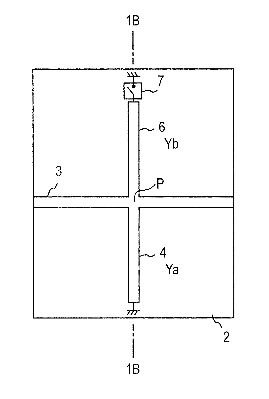
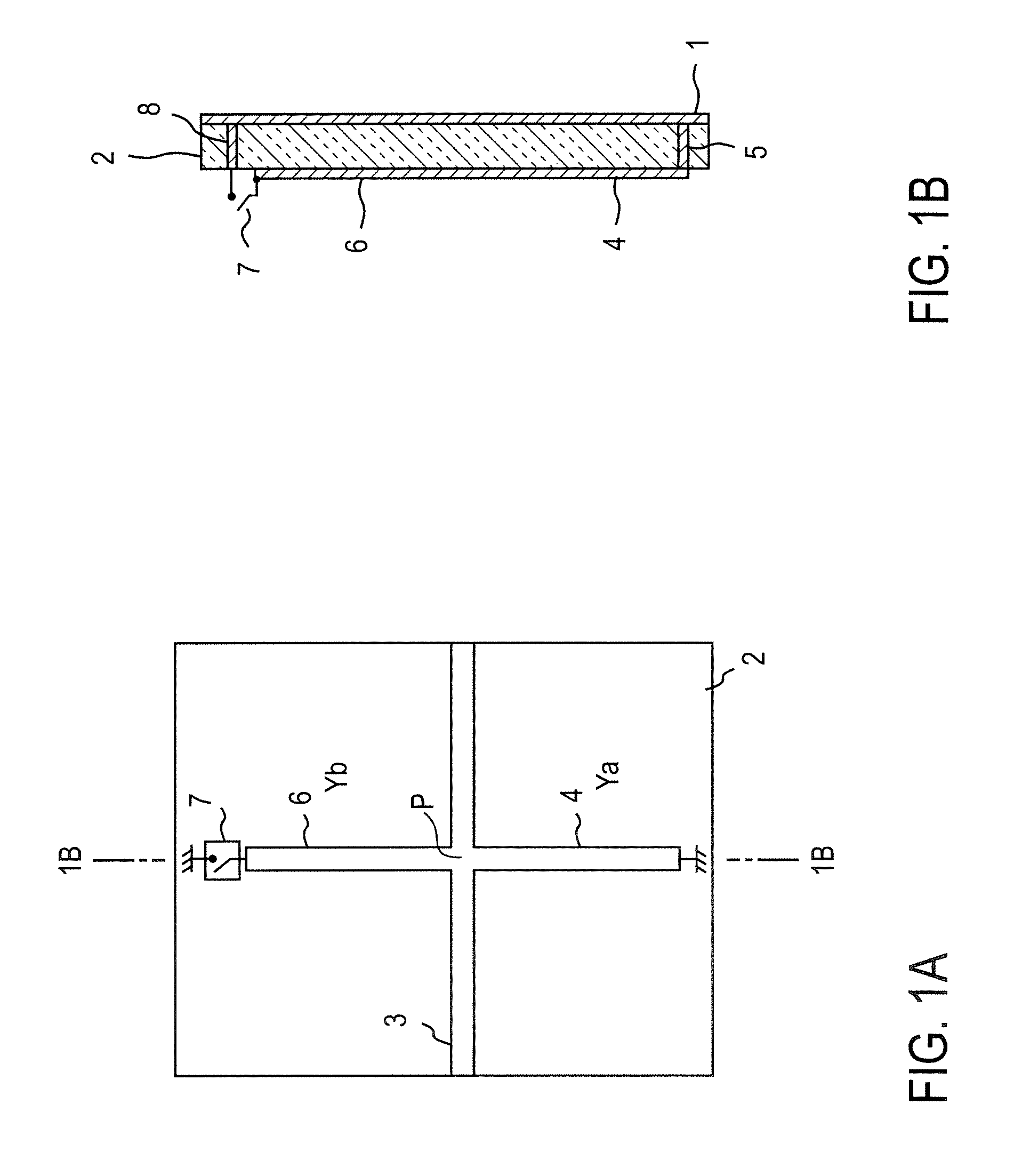
[0073]FIG. 1 shows a resonator having a microstrip line structure according to the present invention. FIG. 1A is a plan view, and FIG. 1B is a cross-sectional view taken along the line 1B-1B in FIG. 1A. An input / output line 3 is formed on the front surface of a dielectric substrate 2, and the back surface of the dielectric substrate 2 is grounded via a ground conductor 1. A high-frequency signal is input to one end of the input / output line 3. In this example, a first resonator 4 is connected to the input / output line 3 at one end thereof, extends in a direction perpendicular to the input / output line 3 and is grounded to the ground conductor 1 at the other end via a conductor passing through an interlayer connection (referred to as via hole hereinafter) 5. The characteristic impedance of the first resonator 4 is Z0.

[0074]One end of a second resonator 6 is connected to the input / output line 3 at the point of connection of the one end of the first resonator 4 to the input / output line 3....

second embodiment

[0118]According to the first embodiment described above, a variable resonator having a wide range of variation of frequency can be provided. However, the interval between the resonance frequencies is relatively wide, such as integral multiples of the fundamental frequency. As a second embodiment, there will be described examples of a variable resonator that has a resonance frequency capable of being more finely resolved (that is, changed in smaller steps) and has a wider range of variation of frequency.

[0119]In advance of the description of the second embodiment, the skin effect, which is utilized also in the prior art shown in FIG. 22, will be described.

[0120]Electric signals transmitted through a resonance line are more likely to be concentrated at the outer periphery of the resonance line as the frequency increases. This is due to the skin effect of high-frequency signals. In the case where an electric signal is transmitted through a conductor, the penetration depth of the signal...

example 1

[0123]FIGS. 9A and 9B show an example in which the skin effect is applied to the variable resonator according to the present invention, thereby increasing the resolution of the variable resonance frequency.

[0124]A dielectric substrate 90 has a rectangular strip shape in a plan view, and an input / output line 3 formed on the dielectric substrate 90 and extends in parallel with the shorter sides thereof at about the middle of the longer sides thereof. On one side of the input / output line 3, a first resonator 4 is connected perpendicularly to the input / output line 3 at about the middle of the input / output line 3. A second resonator 6 is similarly connected on the other side of the input / output line 3.

[0125]In this example 1, the first resonator 4 and the second resonator 6 have shapes that exhibit the skin effect and have an increased resolution of the resonance frequency. The resonance line of the first resonator 4 comprises a combination of two kinds of lines including a first line 41...


PUM


Abstract

A variable resonator has a dielectric substrate 2, an input / output line 3 formed on the dielectric substrate 2, a first resonator 4 that has one end connected to the input / output line 3 and the other end grounded, and a second resonator that has one end connected to the input / output line 3 at the point of connection of the one end of the first resonator 4 and the other end grounded via a terminal switch 7. When the terminal switch 7 is turned off, resonance occurs at a frequency at which the sum of the line lengths of the first resonator 4 and the second resonator 6 equals to a quarter of the wavelength. When the terminal switch 7 is turned on, resonance occurs at a frequency at which a half of the sum of the line lengths equals to a quarter of the wavelength.

Description

TECHNICAL FIELD[0001]The present invention relates to a line-type variable resonator that is mounted on a radio communications device, for example, and constitutes a filter or the like. In particular, it relates to a variable resonator that has a wide range of variable frequency and a low loss.BACKGROUND ART[0002]In the field of radio communications using high-frequency signals, required signals are separated from unnecessary signals by extracting signals of a particular frequency from a great amount of signals. The circuit that serves this function is generally referred to as filter and is mounted on many radio communications devices. A resonator of the filter that has a line structure is required to have a line length equal to about a quarter or a half of the wavelength at the resonance frequency. In addition, main design parameters of the resonator, such as the center frequency and the bandwidth, are fixed. As for the case where a radio communications device uses two frequency ba...

Claims


Application Information

Patent Timeline
Patent Type & Authority Patents(United States)
IPC IPC(8): H01P7/08H01P1/203
CPCH01P1/2013H01P1/20381H01P1/2039H01P1/203H01P7/08
Inventor KAWAI, KUNIHIROFUKUDA, ATSUSHIOKAZAKI, HIROSHINARAHASHI, SHOICHI
Owner NTT DOCOMO INC
Why Eureka
Try Eureka