
Cursor control device

a control device and cursor technology, applied in the field of input devices, can solve the problems of unoptimized use of work surface area, one size and shape does not optimally fit all users, and requires considerable work surface area, so as to optimize the dynamic range of the first sensor

Inactive Publication Date: 2010-11-02
ITAC SYST
View PDF25 Cites 24 Cited by
  • Summary
  • Abstract
  • Description
  • Claims
  • Application Information

AI Technical Summary

Benefits of technology

[0019]A number of alternative embodiments of the illumination and imaging optics are possible in which multiple optical and structural functions can be combined into a smaller number of parts in order to lower the assembly cost and simplify the structure. For example, some of the illumination optics and imaging optics can be incorporated into one or more features in or on the dome, multiple optical elements can be molded into a single piece, and mechanical positioning and attachment features can be incorporated into the optical elements and / or the housing in order to hold the components in position and alignment. Refractive, reflective, or diffractive optics and different light source geometries can be used.
[0020]In alternative embodiments, the housing can be configured to lie in a substantially perpendicular or substantially parallel orientation with respect to a plane of the panel, and the dome can have additional features or textures to provide visual and tactile indication of the position and orientation of the sensitive area. Instead of, or in addition to, grazing incident illumination, the sensitive area can be illuminated more normal to its surface by a different configuration of light source and illumination optics. The dome can be textured to give it diffusing properties, which will make the device relatively insensitive to the motion of objects that are not close to, or in contact with, the surface of the dome closest to the user. Additional light sources or decorative textured or colored features can be provided to enhance the aesthetics and ergonomics of the device. Switches or other controls can be integrally combined with the housing and / or dome of the basic cursor positioning device to provide selection or other additional functions in addition to cursor pointing.
[0022]In this cursor control device, the interior of the inner housing can be fluidly sealed from an exterior of the inner housing. This provides an additional degree of protection for components disposed within the inner housing. The outer shell can be removable from the cursor control device, and since the inner housing is sealed the outer shell can be removed and / or replaced without exposing the components disposed within the inner housing to the environment the inner housing remains fluidly sealed when the outer shell is removed.
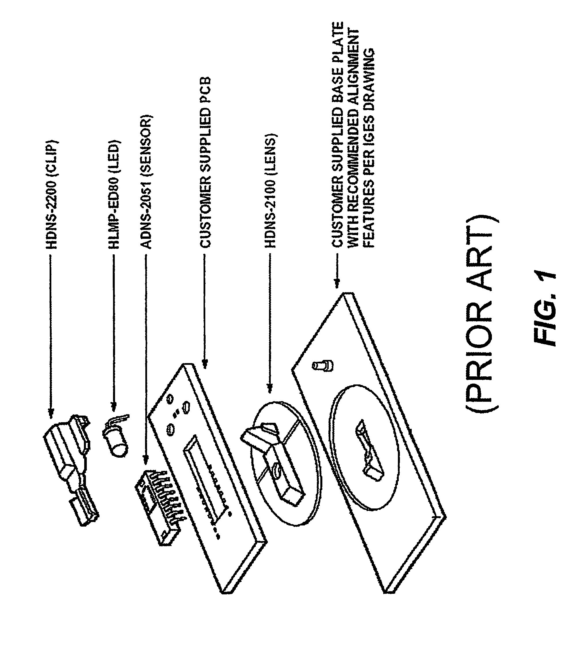
[0024]According to another aspect of the present invention, an optical engine for a cursor control device is provided that includes a housing, an imaging lens element integrally formed into the housing, a light source disposed within the housing for emitting light along an illumination optical axis, and a sensor disposed within the housing for sensing light along an imaging optical axis that intersects the imaging lens element. The optical engine can further include an illumination lens element integrally formed into the housing, wherein the illumination optical axis intersects the illumination lens element. The light source can be a light emitting diode, for example that emits infrared light. The imaging lens element can be such that it focuses light from a focal plane onto the sensor, wherein an angle between the illumination optical axis and the focal plane is in a range from 0 degrees to 45 degrees, more preferably from 15 degrees to 35 degrees, and most preferably 30 degrees. The optical engine can further include a filter element disposed along the imaging optical axis for selectively transmitting light to the sensor. The filter element can be disposed between the imaging lens and the sensor. The filter element can be such that it transmits infrared light and prevents transmission of visible light.
[0049]According to another aspect of the invention, a cursor control device is provided that comprises a first sensor, a light source, and a controller that includes means for receiving intensity information indicative of an intensity of sensed light, and an adaptive illumination control means for controlling the intensity of light emitted by the light source based on the intensity information. The adaptive illumination control means can control the intensity of light in order to optimize the dynamic range of the first sensor. The adaptive illumination control means can control the intensity of light based on a shutter value signal received from the first sensor. The adaptive illumination control means can control the intensity of light based on a contrast signal received from the first sensor. The intensity information can be received from the first sensor, or it can be received from a second sensor in which case the adaptive illumination control means can control the intensity of light in order to optimize the dynamic range of the first sensor.

Problems solved by technology

A major deficiency of the mouse is that it needs to be grasped in the hand, and this often leads to muscular fatigue.
One size and shape does not optimally fit all users.
It requires considerable work surface area to be used, and can fall off of tilted or slippery work surfaces.
Optomechanical mice have considerable problems with dirt getting into the mechanism.
However, although they use modern optical technology, there is still a ball, as well as other moving parts, and hence potential for contamination with dust and liquids, leading to questionable reliability in industrial applications.

Method used


Image

  • Cursor control device
  • Cursor control device
  • Cursor control device

Examples


Embodiment Construction

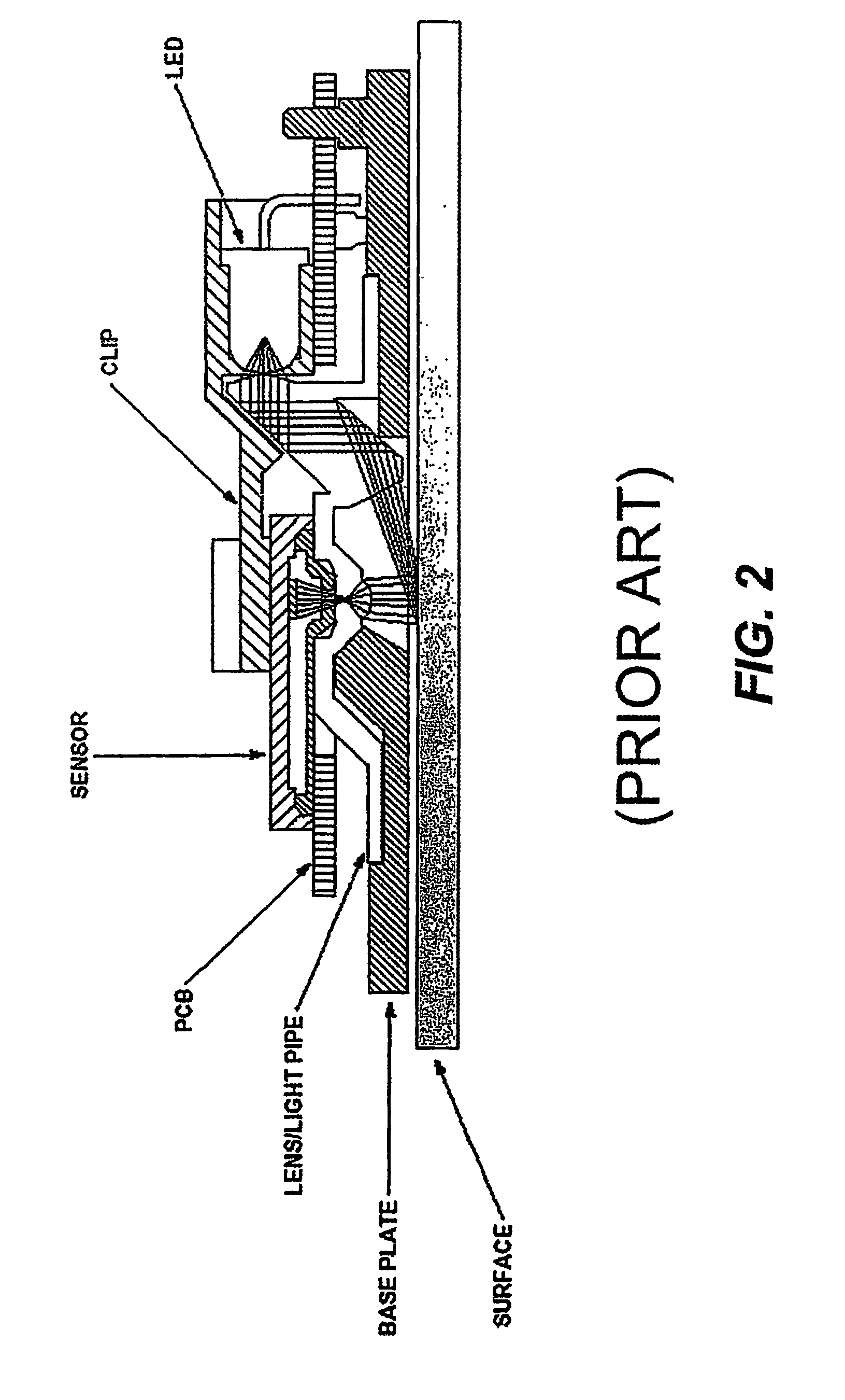
[0086]A cursor control device 10 will first be described with reference to FIG. 3, which shows a generalized block diagram displayed schematically as a side cross-sectional view of a panel-mounted device in order to indicate the general relationship between the elements of the device. The device has a housing 50 which can be held into a hole through panel 100 by one or more attachments 58. Light source 70 emits radiation at a wavelength to which the image sensor 80 is sensitive. Illumination optics 40 redirect and focus the radiation onto optical object plane 300. This object plane 300 is arranged to be proximate or superimposed with a top surface of a dome 30, which provides an optical window. Preferably, in an industrial environment or the like, the dome seals the optical system from the environment as well as provides tactile and visual features with which the user interacts. Imaging optics 88 form a real image of the object plane 300 on the photosensitive portion of image sensor...


PUM


Abstract

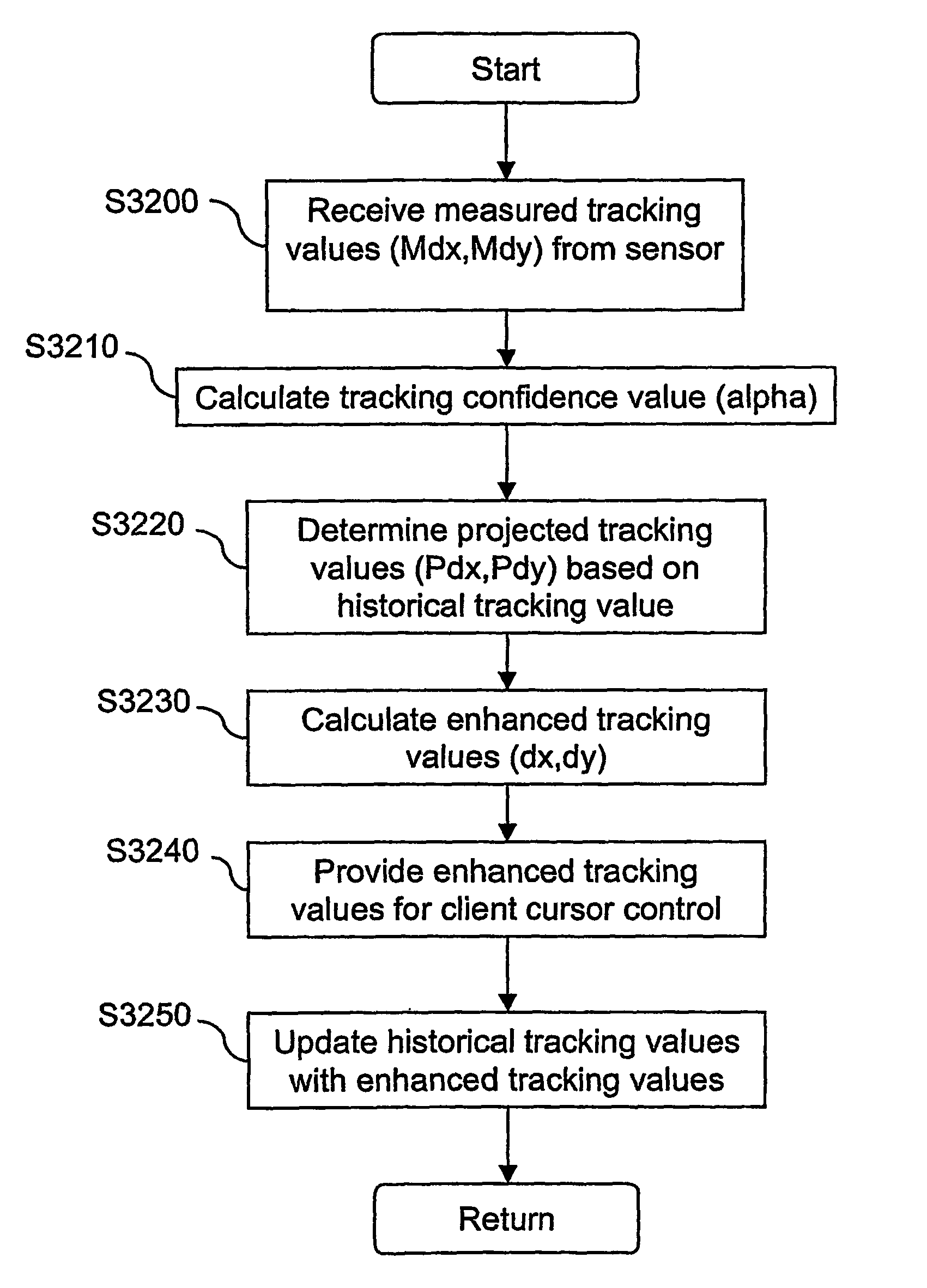
A method of moving the cursor is used in a computer system having a processor operatively coupled to a cursor control device having a light source and an image sensor for optically tracking motion of the cursor control device. The method is executed to move the cursor according to an enhanced tracking value generated based on a measured tracking value, a projected tracking value, and a tracking confidence value based on an illumination value representative of an intensity of light sensed by the sensor.

Description

CROSS-REFERENCE TO RELATED APPLICATIONS[0001]The present application is a 371 of PCT / US03 / 40895 filed Dec. 22, 2003, which claims the benefit of U.S. provisional application No. 60 / 435,933, entitled “Cursor Control Device,” filed Dec. 20, 2002, by inventors Donald P. Bynum and Gregory A. Magel.COPYRIGHT NOTICE[0002]A portion of the disclosure of this patent document contains material which is subject to copyright protection. The copyright owner has no objection to the facsimile reproduction by anyone of the patent document or the patent disclosure as it appears in the Patent and Trademark Office patent file or records, but otherwise reserves all copyright rights whatsoever.FIELD OF THE INVENTION[0003]This invention relates to input devices for controlling computers or computer-controlled machinery or equipment. More specifically, it relates to a pointing device for controlling the position of a cursor on the display screen of a computer or computer-controlled machinery or equipment....

Claims


Application Information

Patent Timeline
Patent Type & Authority Patents(United States)
IPC IPC(8): G09G5/00G06F3/03G06F3/033
CPCG06F3/0317G06F3/03547G06F3/0421G06F2203/0338G06F3/0312G06F3/0321
Inventor BYNUM, DONALD P.MAGEL, GREGORY A.DAWES, ROBERT LEOMOORE, LARRY V.AHMED, MINHAJ
Owner ITAC SYST
Learn More