
Hybrid techniques for memory virtualization in a computer system

a computer system and memory virtualization technology, applied in the field of hybrid techniques for memory virtualization in the computer system, can solve the problems of poor performance, higher performance, and application cannot directly address physical memory

Active Publication Date: 2010-11-02
ORACLE INT CORP
View PDF14 Cites 18 Cited by
  • Summary
  • Abstract
  • Description
  • Claims
  • Application Information

AI Technical Summary

Benefits of technology

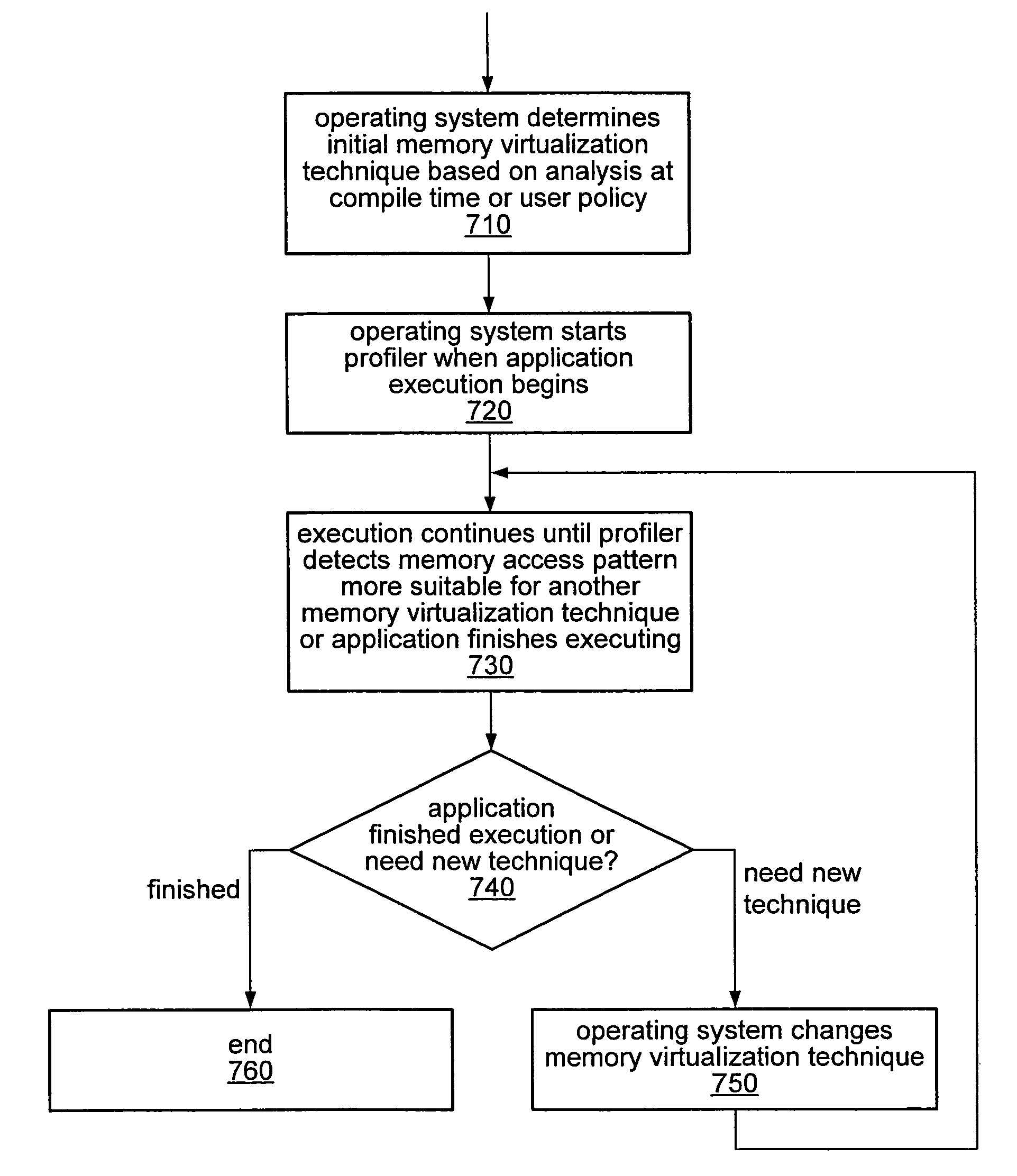
"The patent describes a system and method for optimizing memory virtualization and address translation for applications running on a processor. The system uses different techniques for different applications or components within a single application. The techniques may be selected based on the workload, user policy, or the configuration of available memory. The patent also describes a hybrid technique that combines different basic techniques or variations of them for different applications or memory regions. The technical effects of the patent include improved performance and efficiency in memory virtualization and address translation for applications running on a processor."

Problems solved by technology

Typically, the application cannot address physical memory directly but only after going through the translation process.
For example, a particular technique may result in very poor performance under certain workloads, while, under the same workload, a different technique may result in higher performance.
Similarly, a particular technique may result in very high performance for certain applications and poor performance for others.

Method used


Image

  • Hybrid techniques for memory virtualization in a computer system
  • Hybrid techniques for memory virtualization in a computer system
  • Hybrid techniques for memory virtualization in a computer system

Examples


Embodiment Construction

Introduction

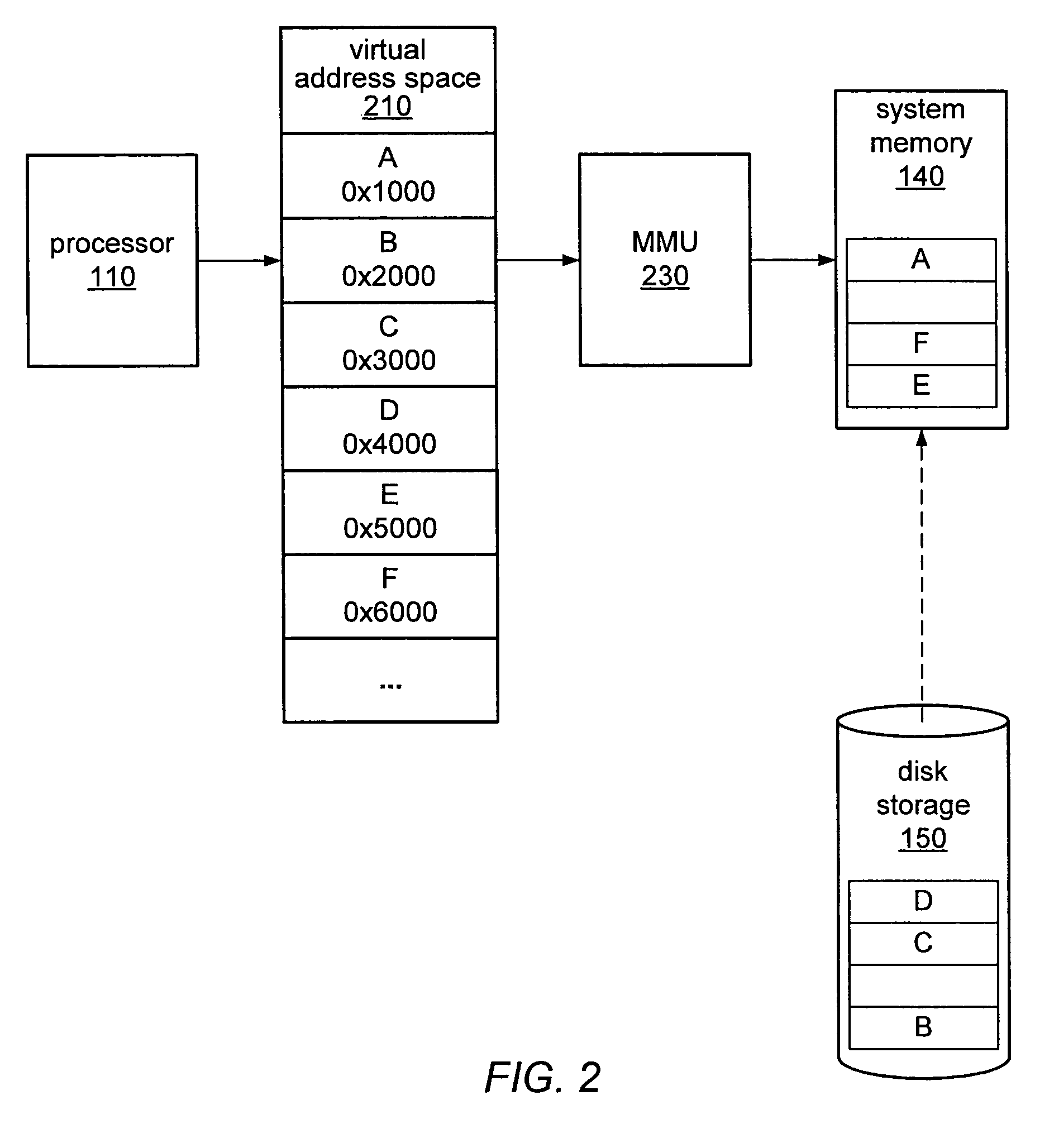
[0025]Many modern computer systems have adopted a hierarchical memory system, typically involving at least two or three layers. An example of such a configuration is illustrated by FIG. 1. In this example, a microprocessor 110 may be attached to a level 1 (L1) cache 120 and then to a level 2 (L2) cache 130. The L1 cache 120 may be fabricated on the same semiconductor device as processor 110, and so may provide very fast data access for processor 110, while the L2 cache 130 may or may not be a separate semiconductor storage device and may have longer access times than L1 cache 120. The next device in the memory hierarchy, in this example, is random access memory (RAM) 140. This may also be referred to by a variety of other names, such as physical memory, system memory, main memory, or internal storage. RAM 140 may be implemented as a semiconductor device typically distinct from microprocessor 110, but may be significantly slower than L1 cache 120 and L2 cache 130. RAM 140...


PUM


Abstract

A computer system may employ a first memory virtualization and corresponding virtual-to-physical address translation technique for a first application executing on a processor and a second memory virtualization and corresponding virtual-to-physical address translation technique for a second application executing on the same processor transparent to the first application. Different virtualization and corresponding translation techniques may be employed on a per-thread basis, rather than a per-application basis. Different virtualization and corresponding translation techniques may be employed for accesses to different ranges of virtual or corresponding physical addresses. Different virtualization and corresponding translation techniques may employ different page sizes. A first or second virtualization and corresponding translation technique may include page-based, segment-based, or function-based virtual-to-physical address translation. The selection of a first or second memory virtualization and corresponding address translation technique may be dependent on a predicted workload and / or on a user policy.

Description

[0001]The U.S. Government has a paid-up license in this invention and the right in limited circumstances to require the patent owner to license others on reasonable terms as provided for by the terms of Contract No. NBCH3039002 awarded by the Defense Advanced Research Projects Agency (DARPA).BACKGROUND OF THE INVENTION[0002]1. Field of the Invention[0003]This invention relates to computer systems, and more specifically to techniques for memory virtualization.[0004]2. Description of the Relevant Art[0005]Modern computer systems provide a feature known as “virtual memory”, or “virtual memory addressing”, a technique of memory address translation between addresses used in a software application and physical memory addresses. These translation mechanisms allow the addresses used by the application to be independent of the addresses of the underlying physical memory. Thus, an application may access addresses that translate to locations in a processor's local or main memory (e.g., the CPU...

Claims


Application Information

Patent Timeline
Patent Type & Authority Patents(United States)
IPC IPC(8): G06F12/00G06F9/26G06F9/34
CPCG06F12/109G06F2212/652G06F2212/683G06F12/1036G06F12/1045
Inventor MANCZAK, OLAFVICK, CHRISTOPHER A.PALECZNY, MICHAEL H.FREEMAN, JAY R.GUSTAFSON, PHYLLIS E.
Owner ORACLE INT CORP
Learn More