Device for support of an adjusting ring which encompasses at a distance a circular blade carrier

a technology of adjusting ring and support, which is applied in the direction of machines/engines, mechanical equipment, liquid fuel engines, etc., can solve the problems of adjusting ring itself wear, affecting the operation of the compressor, so as to achieve the effect of simple fitting and removal and larger tolerances

Inactive Publication Date: 2010-11-09
SIEMENS AG
View PDF13 Cites 12 Cited by
  • Summary
  • Abstract
  • Description
  • Claims
  • Application Information

AI Technical Summary

Benefits of technology

[0006]Accordingly, the object of the present invention is the creation of a wear-free and reliable device for support of an adjusting ring, which encompasses at a distance a basically circular blade carrier, for adjusting the radially extending blades of a ring which are rotatable around their longitudinal axis.
[0008]By the proposed embodiment, therefore, a support for the adjusting ring can be disclosed which enables only a rotational movement of the adjusting ring which is orientated in the circumferential direction, and which suppresses a tilting or partial displacement, as the case may be, in the axial direction. By this, wear on the adjusting ring, on the fastening of the single-arm levers, and on the rotatable rollers, which are rollable in the circumferential direction on the adjusting ring or on the blade carrier, is avoided. At the same time, a constantly symmetrical adjustment of the blades of a ring of a turbo-engine is ensured so that no losses occur in the medium which flows around the blades of the ring of the turbo-engine. The efficiency of the turbo-engine is permanently maintained.
[0011]Preferably, each roller is rotatable around a roller axis which is parallel to the center axis. This enables the use of cylindrical surfaces on the adjusting ring or on the blade carrier, upon which similarly cylindrical rollers are rollable.
[0012]Each lever is expediently screwed to the blade carrier so that an especially simple fitting and removal of the lever or levers, as the case may be, on the blade carrier is possible. In order to enable larger tolerances during manufacture of the levers and to adjust a defined pretensioning which presses the roller, which is rotatably mounted on the lever, onto the inner side of the adjusting ring or onto the blade carrier, each lever has at least one elongated hole, which extends in the tangential direction, for accommodating the screwed fitting. As a result of this, the desired pretensioning of the lever can be steplessly adjusted since the free flexible length of each lever between the ends can be varied.
[0013]In order to prevent a slipping off of the rollers from the inner side of the adjusting ring, an endlessly encompassing annular groove is provided on the inner side of the adjusting ring, with a groove base upon which the rollers are rollable. The groove walls of the annular groove guide the rollers and so prevent the slipping off of the rollers from the bearing surface.

Problems solved by technology

This leads on one hand to flow losses in the compressor on account of the asymmetrically or differently adjusted stator blades of the ring, as the case may be, when viewed over the circumference, and on the other hand also leads to wear on the support of the adjusting ring and also on the adjusting ring itself.

Method used


Image

  • Device for support of an adjusting ring which encompasses at a distance a circular blade carrier
  • Device for support of an adjusting ring which encompasses at a distance a circular blade carrier
  • Device for support of an adjusting ring which encompasses at a distance a circular blade carrier

Examples


Embodiment Construction

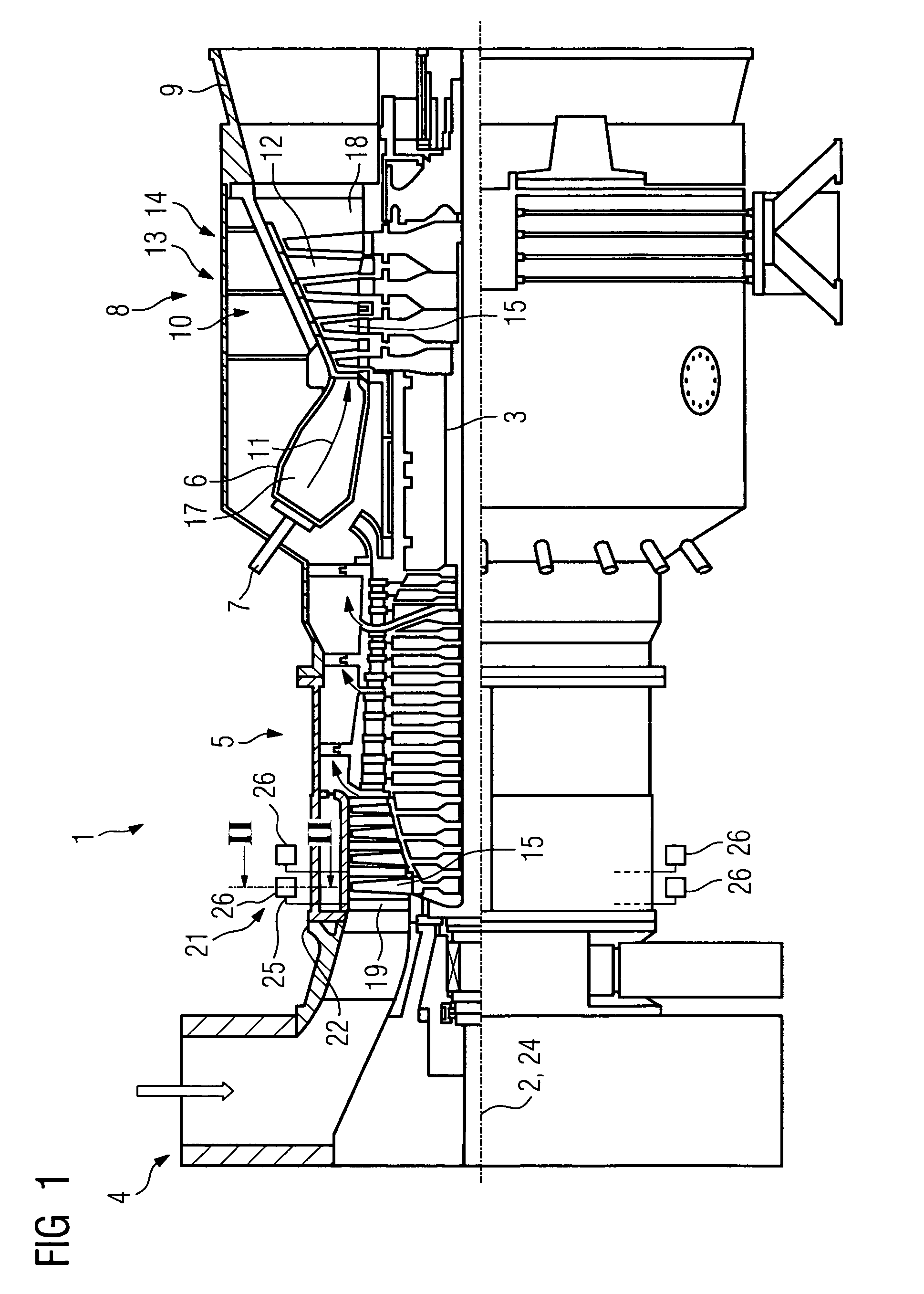
[0020]FIG. 1 shows a gas turbine 1 in a longitudinal partial section. Inside, it has a rotor 3, which is also designated as a turbine rotor, which is rotatably mounted around a rotational axis 2. An intake duct 4, a compressor 5, a toroidal annular combustion chamber 6 with a plurality of burners 7 which are arranged axially symmetrically to each other, a turbine unit 8 and an exhaust duct 9, are arranged in series along the rotor 3. The annular combustion chamber 6 forms a combustion space 17 which communicates with an annular hot gas passage 18. There, four turbine stages 10, which are connected one behind the other, form the turbine unit 8. Each turbine stage 10 is formed from two blade rings. Viewed in the flow direction of a hot gas 11 which is produced in the annular combustion chamber 6, a row 14 which is formed from rotor blades 15 follows a stator blade row 13 in each case in the hot gas passage 18. The stator blades 12 are fastened on the stator, whereas the rotor blades 1...


PUM


Abstract

The invention relates to a device for support of an adjusting ring which encompasses at a distance a basically circular blade carrier, which adjusting ring is rotatable in the circumferential direction around a center axis which is identical with the blade carrier, in order to adjust radially extending blades of a ring of a turbo-engine, wherein a plurality of levers are provided between the blade carrier and the adjusting ring, which levers are distributed over the circumference, extend tangentially in each case, and which on their free ends have a rotatable roller in each case, which are rollable in the circumferential direction on the adjusting ring or on the blade carrier. According to the invention, the lever is tightly clamped on one side to disclose a wear-free and reliable device for support of an adjusting ring which encompasses at a distance a circular blade carrier.

Description

CROSS REFERENCE TO RELATED APPLICATIONS[0001]This application claims the benefits of European Patent application No. 06000027.0 filed Jan. 2, 2006. All of the applications are incorporated by reference herein in their entirety.FIELD OF INVENTION[0002]The invention relates to a device for support of an adjusting ring which encompasses at a distance a basically circular blade carrier, which adjusting ring is rotatable in the circumferential direction around a center axis identical with the blade carrier in order to adjust radially extending stator blades of a ring of a turbo-engine.BACKGROUND OF THE INVENTION[0003]A device of such type originates, for example, from U.S. Pat. No. 5,549,448. In order to adjust the radially extending stator blades of a stator blade ring of a compressor, an adjusting ring, which is concentric to the center axis of the compressor, encompasses its center casing. Each stator blade of the stator blade ring, which is rotatable around its longitudinal axis, is ...

Claims


Application Information

Patent Timeline
Patent Type & Authority Patents(United States)
IPC IPC(8): F01D17/16F04D29/56
CPCF01D17/162F04D29/563F05D2260/50
Inventor HARTMANN, MARTINKUPPER, ALEXANDRALOCH, WALTERSHEVCHENKO, VADIM
Owner SIEMENS AG
Why Eureka
Try Eureka