Imaging lens and imaging apparatus

a technology of imaging apparatus and lens, applied in the field of imaging lens and imaging apparatus, can solve the problem of high manufacturing cost of imaging lens, and achieve the effects of low manufacturing cost, high optical performance and small siz

Active Publication Date: 2010-11-09
JIANGXI OFILM OPTICAL CO LTD
View PDF6 Cites 46 Cited by
  • Summary
  • Abstract
  • Description
  • Claims
  • Application Information

AI Technical Summary

Benefits of technology

[0010]The invention has been made in order to solve the above-mentioned problems, and an object of the invention is to provide an imaging lens that has a wide angle of view, a small size, a small F number, a low manufacturing cost, and a high optical performance, and an imaging apparatus including the imaging lens.(First Aspect)
[0012]According to the imaging lens of the first aspect of the invention, it is possible to obtain an optical system having a wide angle of view, a small size, a small F number, and a high optical performance by appropriately selecting the structure of each lens, as described above. In addition, since an aspheric surface is not necessarily used, it is possible to reduce manufacturing costs. Further, in the imaging lens according to the first aspect of the invention, since the Abbe number of the fourth lens that is arranged in the vicinity of the aperture diaphragm and has a strong negative power is equal to or less than 30, it is possible to effectively reduce chromatic aberration. In addition, since the imaging lens is configured so as to satisfy Conditional expression 1, it is easy to correct distortion and field curvature and it is possible to increase the angle of view.
[0018]According to the imaging lens of the second aspect of the invention, it is possible to obtain an optical system having a small size, a small F number, and a high optical performance by appropriately selecting the structure of each lens, as described above. In addition, since an aspheric surface is not necessarily used, it is possible to reduce manufacturing costs. In particular, in the imaging lens of the second aspect of the invention, when the object-side surface and the image-side surface of each of the second and third lenses are configured as described above, it is easy to correct spherical aberration and it is possible to obtain an optical system having a small F number. In addition, when the Abbe numbers of the second and fourth lenses are selected as described above, it is easy to correct chromatic aberration and it is possible to achieve a high optical performance.
[0025]According to the imaging lens of the first aspect of the invention, in a lens system including at least six lenses, for example, the shape and power of each lens and the material forming each lens are appropriately set to satisfy Conditional expression 1. Therefore, it is possible to achieve an imaging lens having a wide angle of view, a small size, a small F number, a low manufacturing cost, and a high optical performance, and an image apparatus including the imaging lens.
[0026]According to the imaging lens of the second aspect of the invention, in a lens system including at least six lenses, for example, the shape and power of each lens and the material forming each lens are appropriately set. Therefore, it is possible to achieve an imaging lens having a small size, a small F number, a low manufacturing cost, and a high optical performance, and an image apparatus including the imaging lens.

Problems solved by technology

In addition, since an aspheric lens is used, the imaging lens has a high manufacturing cost.

Method used


Image

  • Imaging lens and imaging apparatus
  • Imaging lens and imaging apparatus
  • Imaging lens and imaging apparatus

Examples


first embodiment

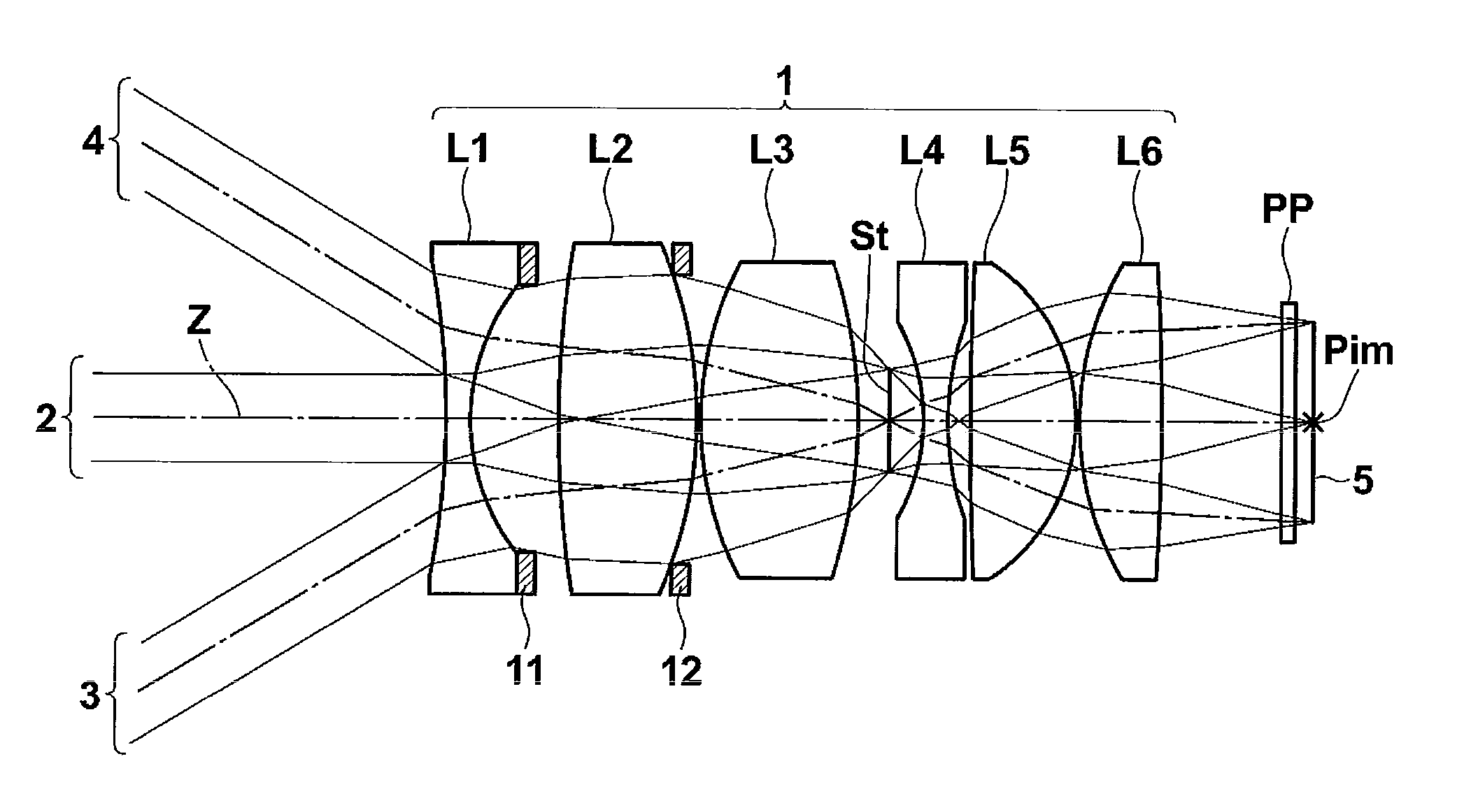
[0058]The imaging lens 1 according to a first embodiment shown in FIG. 1 includes a first lens L1 that has a negative power and includes a concave surface facing an image side, a second lens L2 having a positive power, a third lens L3 having a positive power, an aperture diaphragm St, a fourth lens L4, which is a biconcave lens having a negative power, a fifth lens L5 that has a positive power and includes a convex surface facing the image side, and a sixth lens L6 that has a positive power and includes a convex surface facing an object side. The first to sixth lenses are arranged in this order from the object side. The imaging lens 1 includes a relatively small number of lenses, for example, a minimum of six lenses. Therefore, it is possible to reduce the total length of the imaging lens in the optical axis direction. FIG. 1 does not show the shape or size of the aperture diaphragm St, but shows the position of the aperture diaphragm St on the optical axis Z.

[0059]Since the first l...

second embodiment

[0097]An imaging lens 1 according to a second embodiment shown in FIG. 12 includes a first lens L1 that has a negative power and includes a concave surface facing an image side, a second lens L2, which is a biconvex lens having a positive power, a third lens L3 having a positive power, an aperture diaphragm St, a fourth lens L4, which is a biconcave lens having a negative power, a fifth lens L5 that has a positive power and includes a convex surface facing the image side, and a sixth lens L6 that has a positive power and includes a convex surface facing an object side. The first to sixth lenses are arranged in this order from the object side. The imaging lens 1 includes a relatively small number of lenses, for example, a minimum of six lenses. Therefore, it is possible to reduce the total length of the imaging lens in the optical axis direction. FIG. 12 does not show the shape or size of the aperture diaphragm St, but shows the position of the aperture diaphragm St on the optical ax...

example 1

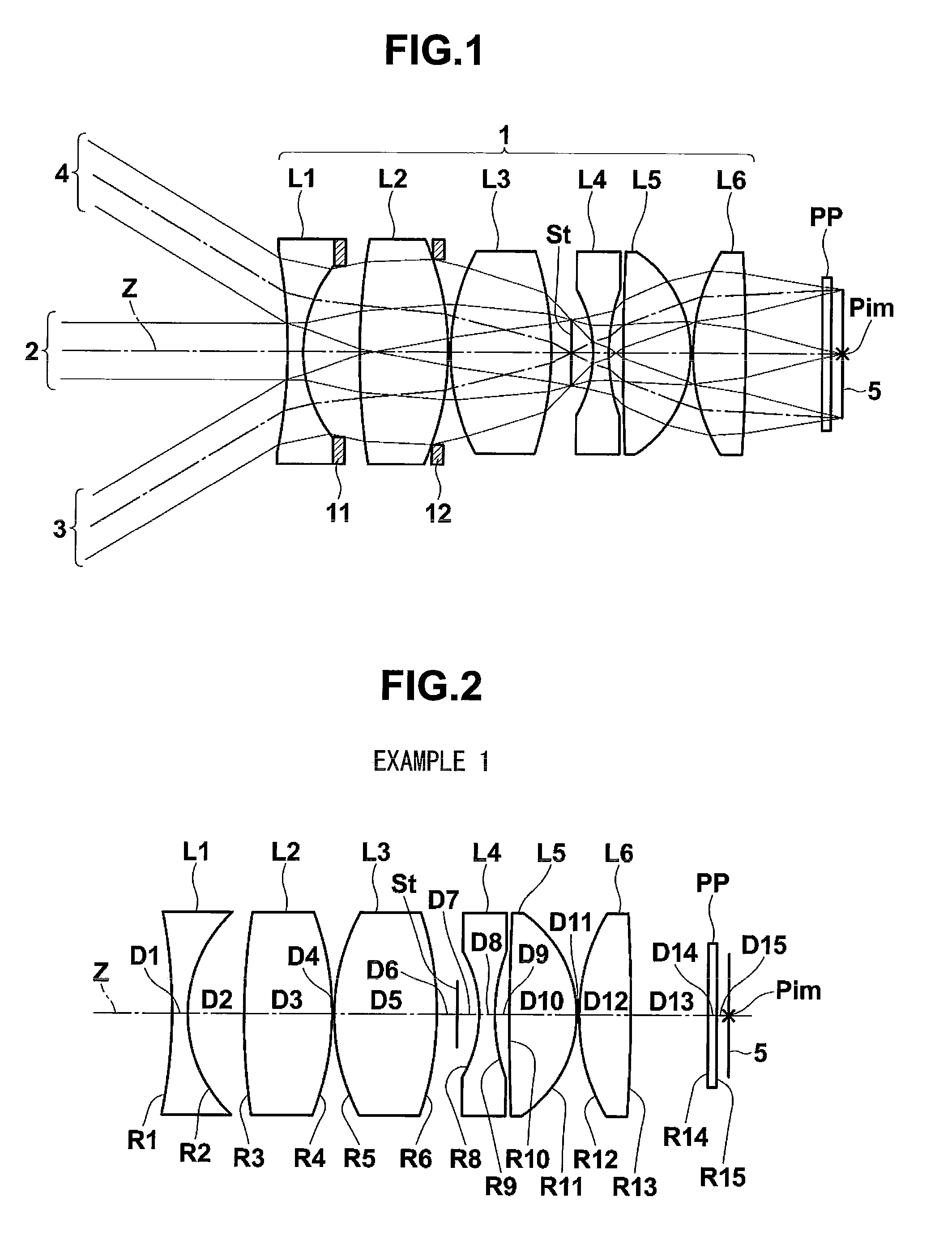
[0158]The structure of an imaging lens according to Example 1 is shown in FIG. 2, and lens data and various data are shown in Table 1.

[0159]

TABLE 1Example 1 Lens dataSiRiDiNdjνdj1−23.430.701.772549.626.152.50330.053.901.883040.84−12.550.1159.584.501.755052.36−14.190.897 (Aperture diaphragm)0.978−5.660.701.922918.998.220.6410 100.173.001.755052.311 −5.390.1012 8.862.301.772549.613 −73.143.4014 ∞0.401.516864.215 ∞0.50Image surface—Example 1 Various dataFno.2.002ω62.4L24.48Bf4.17f5.07f1−6.24f210.48f38.25f4−3.54f56.86f610.36f4567.60IH2.8ED18.29

[0160]In the lens data shown in Table 1, Si indicates an i-th (i=1, 2, 3, . . . ) surface number. In this case, the surface of a component closest to the object side is given number 1, and the surface number is sequentially increased toward the image side. In addition, the lens data shown in Table 1 includes the aperture diaphragm St and the optical member PP.

[0161]In Table 1, Ri indicates the curvature radius of the i-th (i=1, 2, 3, . . . ) surfa...


PUM


Abstract

An imaging lens includes a first lens having a negative power and including a concave surface facing an image side, a second lens having a positive power, a third lens having a positive power, an aperture diaphragm, a fourth lens, which is a biconvex lens having a negative power, a fifth lens having a positive power and including a convex surface facing the image side, and a sixth lens having a positive power and including a convex surface facing an object side, which are arranged in this order from the object side. The Abbe number of a material forming the fourth lens with respect to the d-line is 30 or less. When the focal length of the entire lens system is f and a composite focal length from the fourth lens to the sixth lens is f456, the imaging lens satisfies following conditional expression:1.00<f456 / f<1.88.

Description

CROSS-REFERENCE TO RELATED APPLICATIONS[0001]This application is based upon and claims the benefit of priority from Japanese Patent Application Nos. 2008-260271 and 2008-260272 filed on Oct. 7, 2008; the entire contents of which are incorporated herein by reference.BACKGROUND OF THE INVENTION[0002]1. Field of the Invention[0003]The present invention relates to an imaging lens and an imaging apparatus, and more particularly, to an imaging lens suitable for, for example, an in-vehicle camera, a mobile terminal camera, or a monitoring camera using an imaging device, such as a CCD (charge coupled device) or a CMOS (complementary metal oxide semiconductor), and an imaging apparatus including the imaging lens.[0004]2. Description of the Related Art[0005]In recent years, the size of an imaging device, such as a CCD or a CMOS, has been reduced, and the number of pixels thereof has increased. In addition, the size of the imaging apparatus including the imaging device has been reduced. Theref...

Claims


Application Information

Patent Timeline
Patent Type & Authority Patents(United States)
IPC IPC(8): G02B9/62
CPCG02B9/62G02B13/04
Inventor ASAMI, TARO
Owner JIANGXI OFILM OPTICAL CO LTD
Why Eureka
Try Eureka