
System and method for computationally determining migration of neurostimulation leads

a neurostimulation and migration technology, applied in the field of tissue stimulation systems, can solve the problems of inability to accurately stimulate neural tissue, inability to accurately stimulate the target neural tissue, and easy migration in the epidural spa

Active Publication Date: 2010-11-09
BOSTON SCI NEUROMODULATION CORP
View PDF5 Cites 62 Cited by
  • Summary
  • Abstract
  • Description
  • Claims
  • Application Information

AI Technical Summary

Problems solved by technology

Thus, correct lead placement can mean the difference between effective and ineffective pain therapy.
One of the disadvantages of percutaneous leads, however, is that they are prone to migrating in the epidural space, either over time or as a result of sudden flexion movement.
Lead migration may relocate the paresthesia away from the pain site, resulting in the target neural tissue no longer being appropriately stimulated and the patient no longer realizing the full intended therapeutic benefit.
Lead migration is, however, not the only reason that the therapeutic effects of a previously effective neurostimulation regimen will diminish or simply disappear, which can make diagnosis difficult.
Moreover, even after a physician has determined that lead migration has occurred and that the system must be reprogrammed to accommodate the new positions of the electrodes, conventional neurostimulation systems do not provide the physician with information about the movement of an individual lead, such as how far one lead has moved relative to another lead.
Without such knowledge, the previous stimulation pattern will likely have to be recovered through trial and error and patient feedback, making reprogramming of the electrodes especially difficult.
However, use of conventional imaging systems, which are often not readily available, is inconvenient and costly.
In addition, detection of lead migration via conventional imaging cannot be performed remotely.
However, the use of conventional imaging modalities to detect lead migration is not suitable for automated electrode programmability.

Method used


Image

  • System and method for computationally determining migration of neurostimulation leads
  • System and method for computationally determining migration of neurostimulation leads
  • System and method for computationally determining migration of neurostimulation leads

Examples


Embodiment Construction

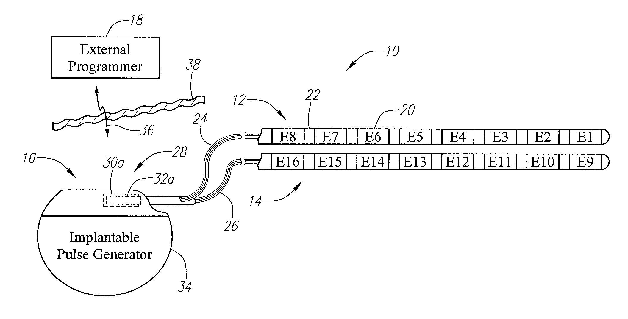
[0030]At the outset, it is noted that the present invention may be used with an implantable pulse generator (IPG), radio frequency (RF) transmitter, or similar electrical stimulator, that may be used as a component of numerous different types of stimulation systems. The description that follows relates to a spinal cord stimulation (SCS) system. However, it is to be understood that the while the invention lends itself well to applications in SCS, the invention, in its broadest aspects, may not be so limited. Rather, the invention may be used with any type of implantable electrical circuitry used to stimulate tissue. For example, the present invention may be used as part of a pacemaker, a defibrillator, a cochlear stimulator, a retinal stimulator, a stimulator configured to produce coordinated limb movement, a cortical and deep brain stimulator, or in any other neural stimulator configured to treat urinary incontinence, sleep apnea, shoulder sublaxation, etc.

[0031]Turning first to FIG...


PUM


Abstract

A tissue stimulation system and computer software and method of monitoring a neurostimulation lead having a plurality of electrodes implanted within a patient (e.g., adjacent the spinal cord) is provided. Neurostimulation lead models are provided, each of which includes estimated electrical parameter data (e.g., electrical field potential data) corresponding to a predetermined position of the neurostimulation lead. Electrical energy is transmitted to or from the electrodes, and electrical parameter data (e.g., electrical field potential data) is measured in response to the transmitted electrical energy. The measured electrical parameter data is compared with the estimated electrical parameter data of each of the neurostimulation lead models, and a position of the neurostimulation lead is determined based on the comparison.

Description

FIELD OF THE INVENTION[0001]The present invention relates to tissue stimulation systems, and more particularly, to systems and methods for determining the migration of neurostimulation leads.BACKGROUND OF THE INVENTION[0002]Spinal cord stimulation (SCS) is a well-accepted clinical method for reducing pain in certain populations of patients. During SCS, the spinal cord, spinal nerve roots, or other nerve bundles are electrically stimulated using one or more neurostimulation leads implanted adjacent the spinal cord. While the pain-reducing effect of SCS is not well understood, it has been observed that the application of electrical energy to particular regions of the spinal cord induces paresthesia (i.e., a subjective sensation of numbness or tingling) that replaces the pain signals sensed by the patient in the afflicted body regions associated with the stimulated spinal regions. Thus, the paresthesia appears to mask the transmission of chronic pain sensations from the afflicted body ...

Claims


Application Information

Patent Timeline
IPC IPC(8): A61N1/00
CPCA61N1/08A61N1/36128A61N1/0551A61N1/36071A61N1/36185
Inventor MOFFITT, MICHAEL A.
Owner BOSTON SCI NEUROMODULATION CORP
Learn More