Method and apparatus for tensile testing and rethreading optical fiber during fiber draw

a technology of tensile testing and rethreading, which is applied in the direction of optical apparatus testing, instruments, manufacturing tools, etc., can solve the problems of reducing the efficiency of rethreading, and unable to achieve online proof testing, so as to facilitate the free travel of fiber, facilitate the rewinding process, and reduce or even eliminate the cost

Inactive Publication Date: 2010-11-16
CORNING INC
View PDF27 Cites 129 Cited by
  • Summary
  • Abstract
  • Description
  • Claims
  • Application Information

AI Technical Summary

Benefits of technology

[0009]In another embodiment, the method further comprises orienting at least a first, second, and third pulley so that, when the aspirator moves said fiber to said second location, the pulleys are disposed along the length of said fiber and on alternating sides of said desired fiber. The second pulley is then moved across the path of the fiber to thereby retain the fiber in contact with the first, second, and third pulleys, thereby causing the fiber to move in a serpentine path.
[0015]Also, because the automatic rewinding methods and apparatus disclosed herein greatly facilitate and speed up the fiber rewinding process, fiber can now be selectively removed during the fiber draw operation if desired without the loss of significant amounts of fiber. For example, if fiber is detected that has a diameter (e.g. fiber or coating diameter) that is out of specification, the defective fiber can be cut, and the bad fiber allowed to be collected and discarded into the aspirator, until good (i.e., in specification) fiber is again detected, after which time the fiber is wound onto the ondraw sceener and onto a fiber storage spool.

Problems solved by technology

However, with the high draw speeds (e.g. greater than 20-25 m / s) employed in some of today's fiber manufacturing operations, such online proof testing has not been achievable.
In addition, because the fiber draw process cannot be stopped, there would be a great deal of lost fiber while the operator rethreaded the online tensile screening equipment.
Also, because of the time involved with threading conventional tensile testing apparatus, using conventional techniques a great deal of fiber would be lost during the rethreading operation.

Method used


Image

  • Method and apparatus for tensile testing and rethreading optical fiber during fiber draw
  • Method and apparatus for tensile testing and rethreading optical fiber during fiber draw
  • Method and apparatus for tensile testing and rethreading optical fiber during fiber draw

Examples


Embodiment Construction

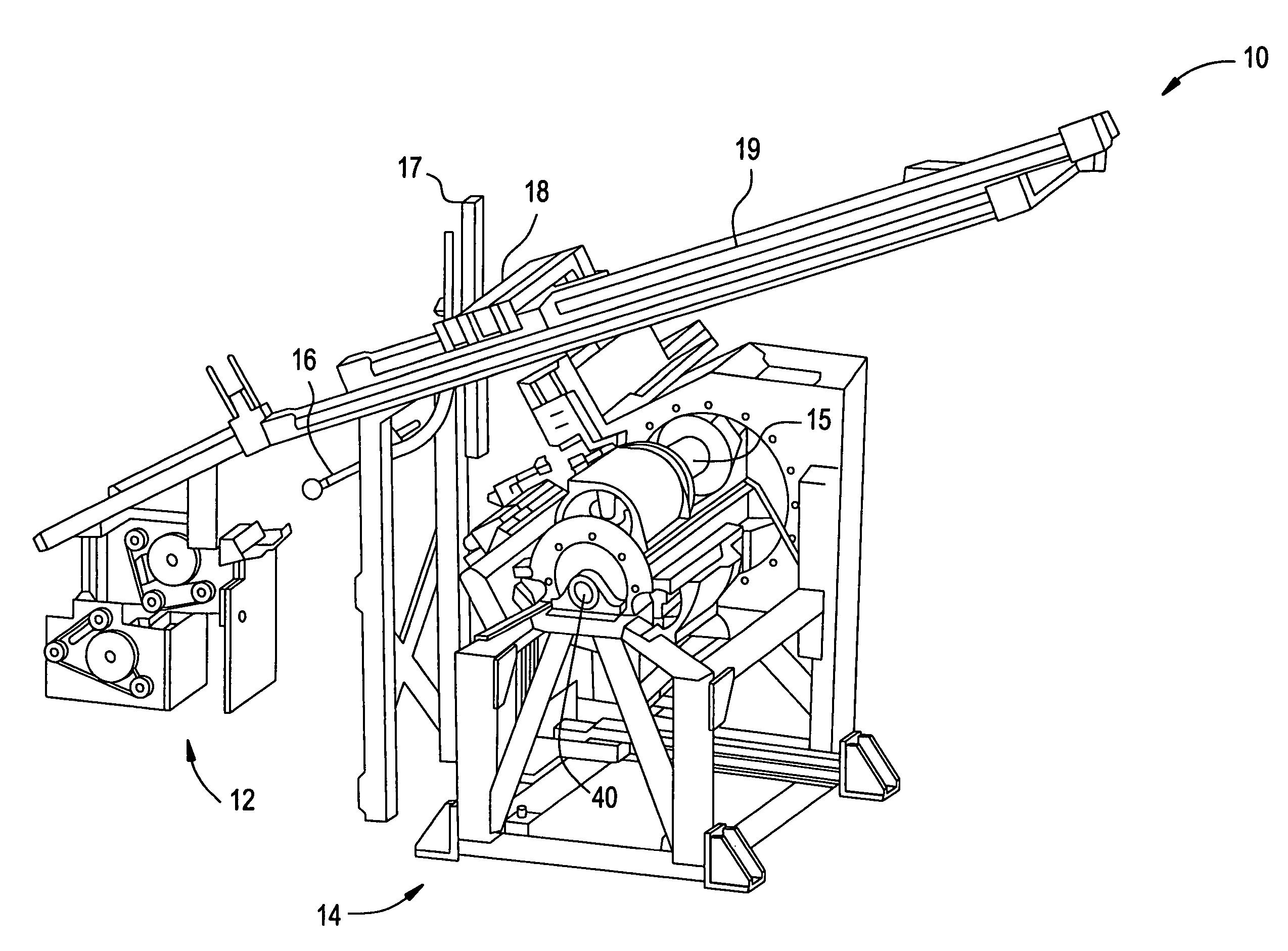
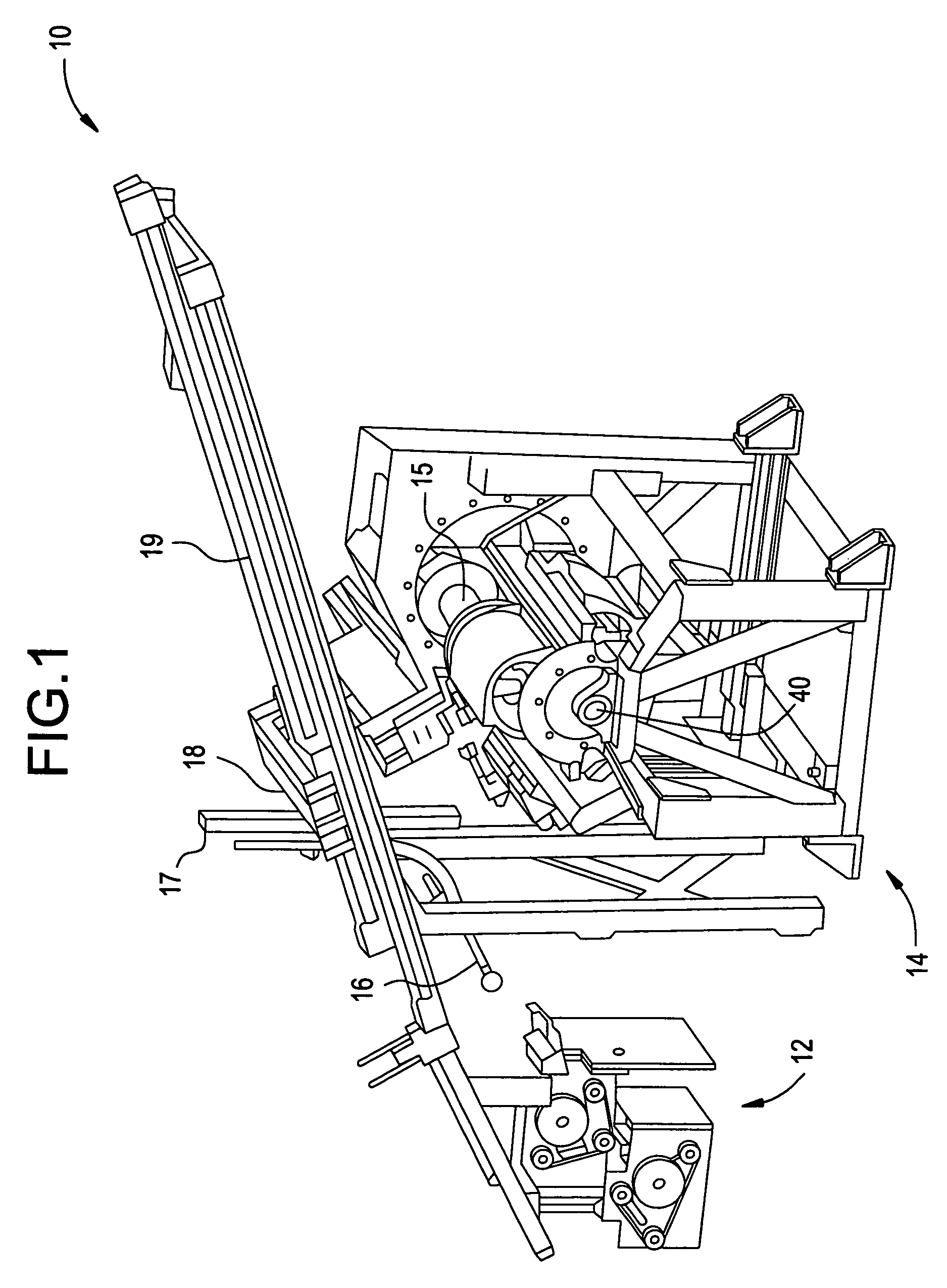
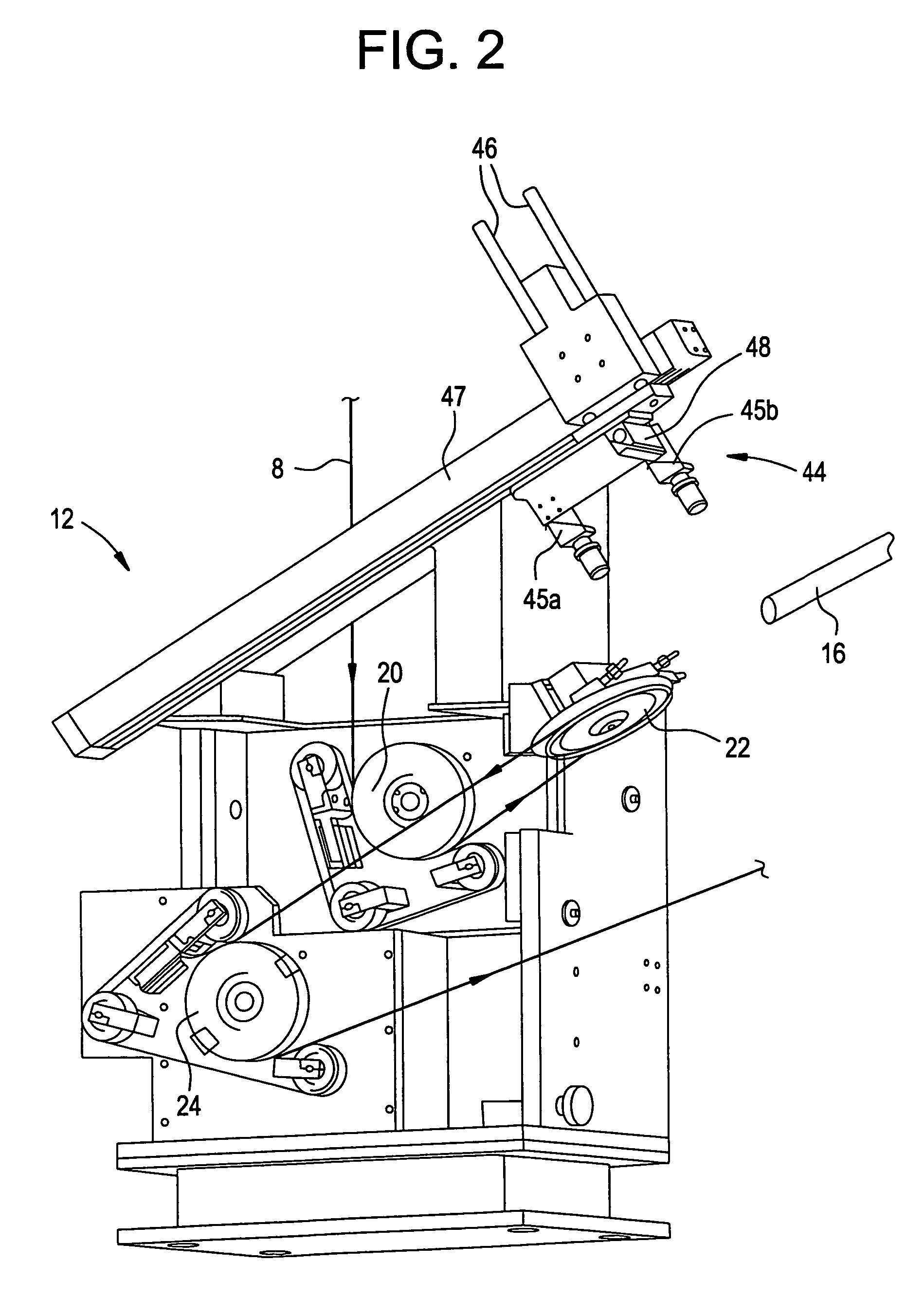
[0024]FIGS. 1, 2, and 3 illustrate a preferred optical fiber winding system 10 in accordance with the present invention, wherein optical fiber 8 is drawn directly from an optical fiber preform or draw blank in an optical fiber draw process. As illustrated in FIG. 1, the major components of the system include a screening section 12, where the fiber is proof tested, and a winding section 14, where the fiber is wound onto a fiber storage spool 15.

[0025]The fiber is mechanically stressed a desired amount (i.e., proof tested) while traveling through screener section 12 which is illustrated in FIGS. 1 and 2. The fiber is then wrapped directly onto spool 15 in fiber winder section 14, illustrated in FIGS. 1 and 3. Spool 15 preferably is a shipping spool which is either to be shipped directly to a customer, which may be a purchaser of optical fiber and / or a cable manufacturing plant to be cabled directly without having to be respooled onto another fiber storage spool. In this way, from the ...


PUM

PropertyMeasurementUnit
tensile stressaaaaaaaaaa
lengthaaaaaaaaaa

Abstract

A method and apparatus for automatic threading and winding of optical fiber onto various components in a fiber draw system, as well as methods and apparatus for conducting online tensile screening of optical fiber at high speeds. In a preferred embodiment, the fiber is tensile tested during fiber draw and wound directly onto a shipping spool to be shipped to a customer. The tensile stress can be imparted to the fiber during the draw process by feeding the fiber through a screener capstan, which works in conjunction with another capstan to impart the desired tensile stress to the fiber during the draw process. Another aspect is a method and apparatus for threading or rethreading of a moving length of fiber through a fiber draw or fiber testing process, in which fiber is wound onto a spool, comprising activating an aspirator to obtain the fiber at a first location and moving said aspirator in at least two dimensions to thereby move the fiber to a second location and thread the fiber through or onto at least one component in the fiber draw or testing process.

Description

CROSS-REFERENCE TO RELATED APPLICATIONS[0001]This is application is a divisional of U.S. application Ser. No. 09 / 733,352,filed Dec. 8, 2000 now abandoned, which claims the benefit of U.S. Provisional Patent Application Ser. No. 60 / 173,401 filed on Dec. 28, 1999, the content of which is relied upon and incorporated herein by reference in its entirety, and the benefit of priority under 35 U.S.C. §120 is hereby claimed.FIELD OF THE INVENTION[0002]The present invention relates to a method and apparatus for automatic threading and winding of optical fiber onto various components in a fiber draw system. The invention further relates to methods and apparatus for conducting online tensile screening of optical fiber at high speeds and winding of the screened optical fiber directly onto optical fiber shipping spools.BACKGROUND OF INTRODUCTION[0003]Optical waveguide fibers (optical fibers) are a well-known transmission medium used in optical communication systems. Fiber draw manufacturing tech...

Claims


Application Information

Patent Timeline
Patent Type & Authority Patents(United States)
IPC IPC(8): B65H65/00B65H57/00G01N3/00B65H54/88B65H67/048C03B37/03C03B37/10G01M11/00G01M11/08G01N3/02G01N3/08G02B6/00
CPCB65H54/88B65H57/003B65H67/048G01M11/088G01N3/08C03B37/032B65H2701/32G01N2203/028C03B2205/40G01N2203/0278C03B37/023
Inventor BUMGARNER, KIRK P.ROBERTS, KENNETH W.TUCKER, DAVID A.
Owner CORNING INC
Why Eureka
Try Eureka