Vascular device with valve for approximating vessel wall

a vascular device and valve technology, applied in the field of vascular devices, can solve the problems of inability to extend sufficiently radially inwardly, ulcers of venous stasis of skin and subcutaneous tissue, and great discomfort and pain for patients, so as to reduce the diameter of the vascular device and reduce the dilation of the vessel

Inactive Publication Date: 2010-11-16
REX MEDICAL LP
View PDF90 Cites 142 Cited by
  • Summary
  • Abstract
  • Description
  • Claims
  • Application Information

AI Technical Summary

Benefits of technology

[0020]reducing the diameter of the vascular device to move the vessel wall radia

Problems solved by technology

In the condition of venous valve insufficiency, the valve leaflets do not function properly as they thicken and lose flexibility, resulting in their inability to extend sufficiently radially inwardly to enable their tips to come into sufficient contact with each other to prevent retrograde blood flow.
Such retrograde blood flow, commonly referred to as reflux, leads to swelling and varicose veins, causing great discomfort and pain to the patient.
Such retrograde blood flow, if left untreated can also cause venous stasis ulcers of the skin and subcutaneous tissue.
Primary venous valve insufficiency is typically a condition from birth, where the vein is simply too large in relation to the leaflets so that the leaflets cannot come i

Method used


Image

  • Vascular device with valve for approximating vessel wall
  • Vascular device with valve for approximating vessel wall
  • Vascular device with valve for approximating vessel wall

Examples


Embodiment Construction

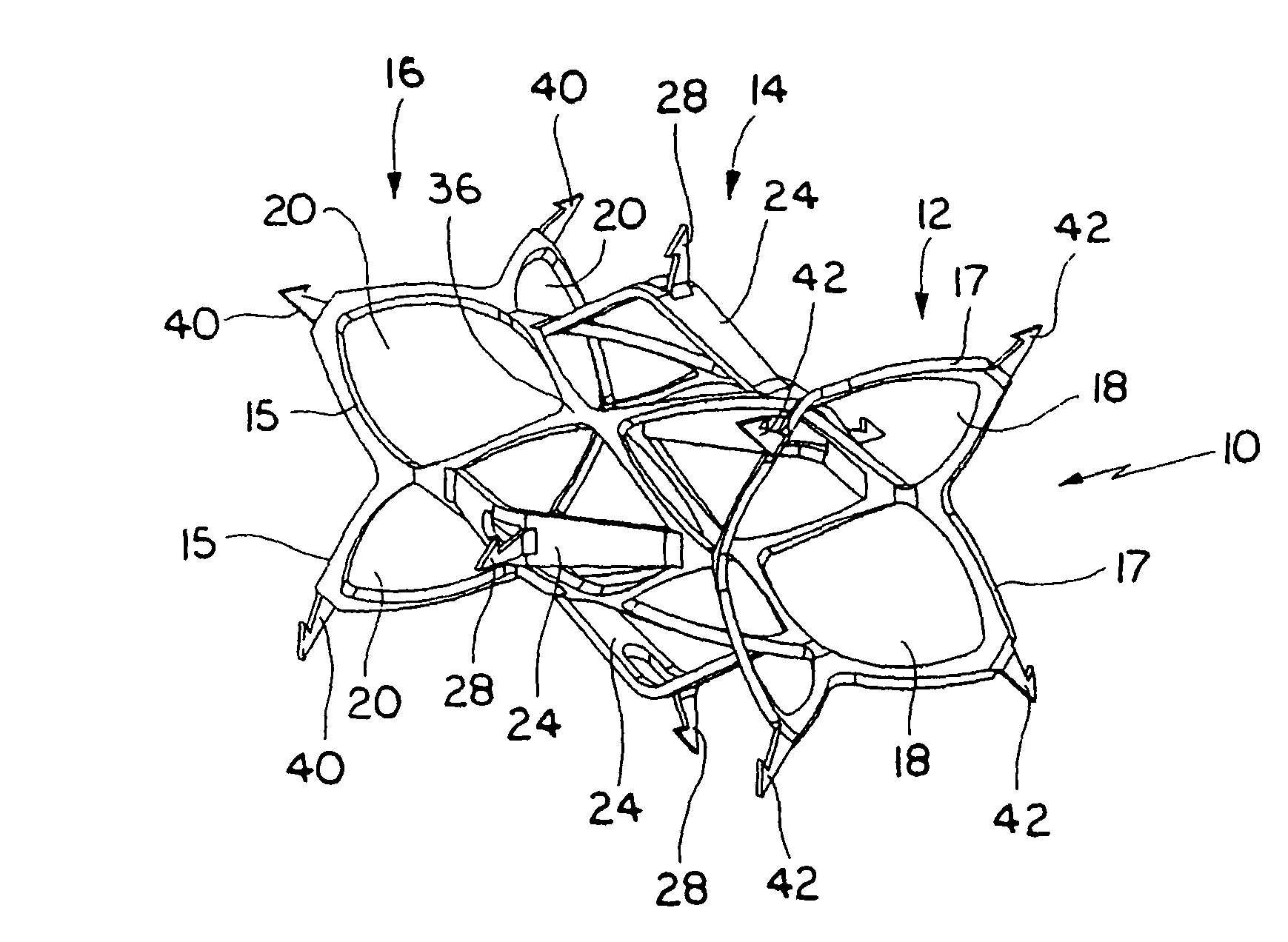
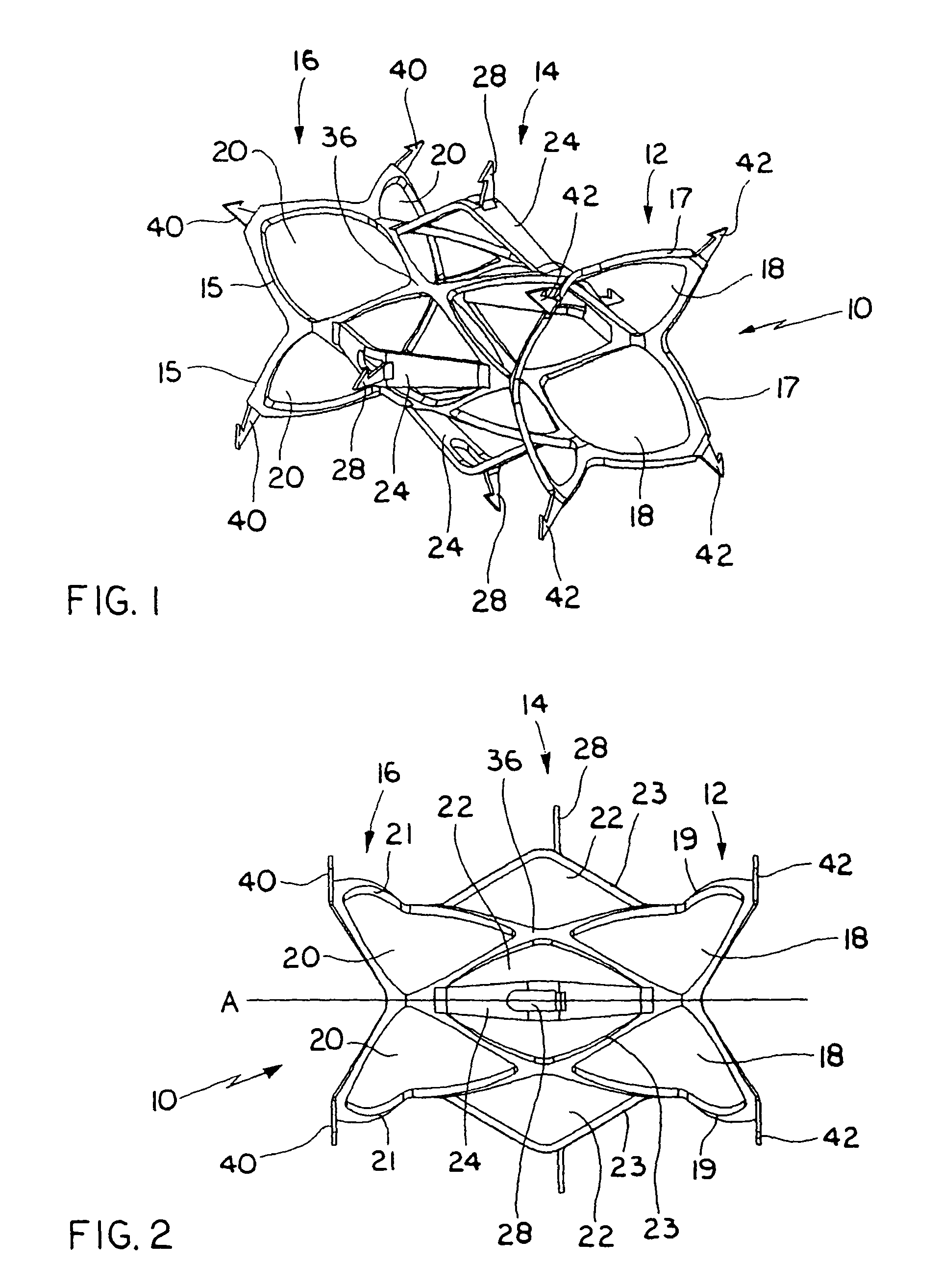
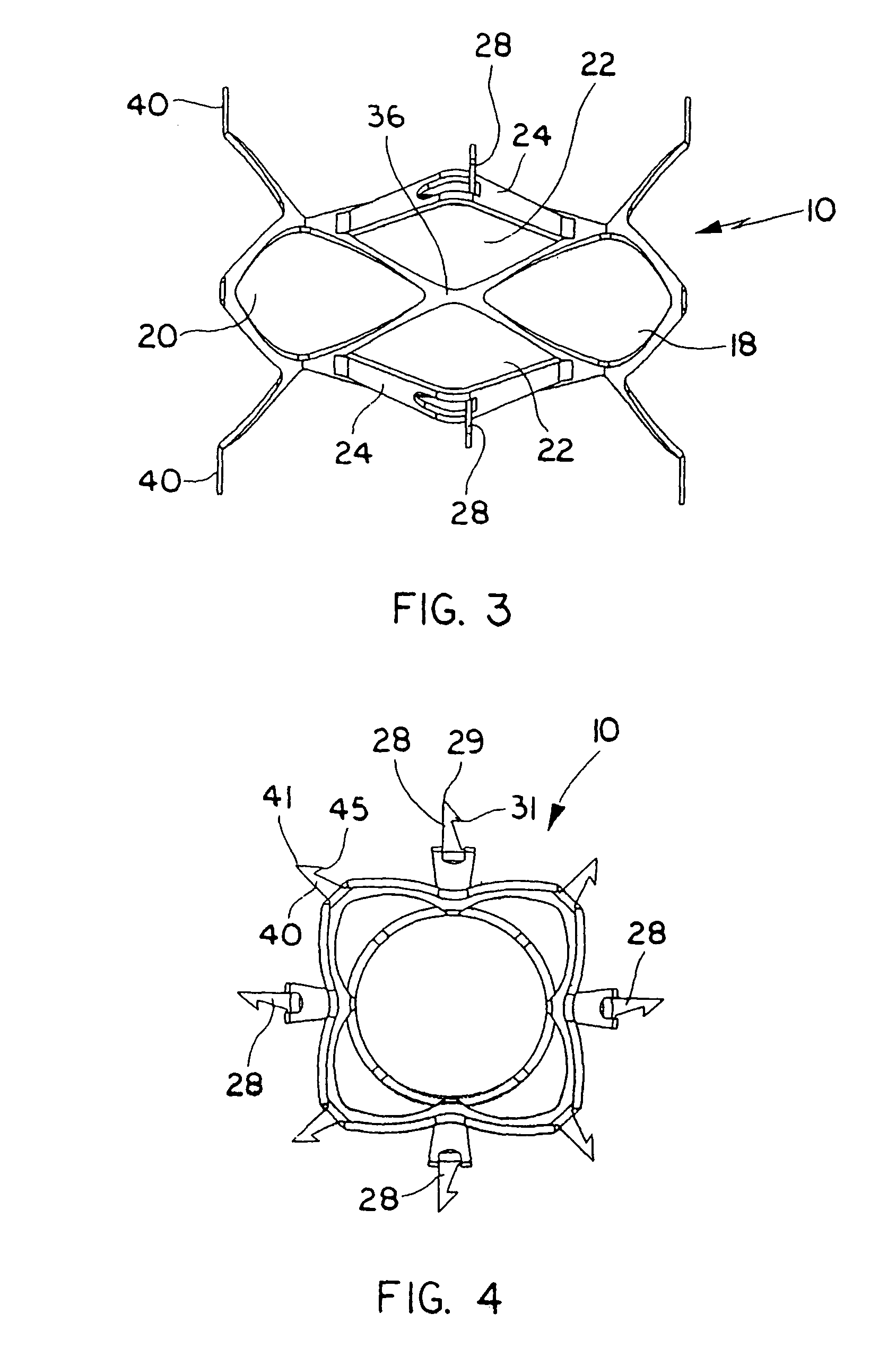
[0104]Referring now in detail to the drawings where like reference numerals identify similar or like components throughout the several views, FIGS. 1-7 illustrate a first embodiment of the vascular device of the present invention and FIGS. 8-11 illustrate a second embodiment of the vascular device of the present invention. The devices, designated generally by reference numerals 10 and 100, are expanded to engage the internal wall of the vessel and contracted to pull the vessel walls radially inwardly. By pulling the vessel wall radially inwardly, the valve leaflets within the vessel are pulled closer together to a functional condition.

[0105]FIGS. 1-4 illustrate vascular device 10 of the first embodiment in the expanded configuration and FIGS. 5-7 illustrate vascular device 10 in the collapsed configuration. Vascular device 10 is preferably composed of a shape memory material, such as a nickel-titanium alloy commonly known as Nitinol, so that in its memorized configuration it assumes...


PUM


Abstract

A vascular device comprising a plurality of vessel engaging members and a valve. The device is movable from a collapsed insertion position having a first diameter to a second expanded position having a second diameter larger than the first diameter. The plurality of vessel engaging members extend outwardly from the device for securely engaging the internal wall of a vessel upon expansion of the device to the second expanded position, wherein the vessel engaging members pull the internal wall of the vessel radially inwardly upon movement of the device from the second expanded position toward a first expanded position having a third diameter greater than the first diameter and less than the second diameter. In the first expanded position the valve is movable between an open position to allow blood flow therethrough to a closed position to prevent blood flow.

Description

[0001]This application is a division of U.S. patent application Ser. No. 10 / 011,345 filed on Dec. 5, 2001 now U.S. Pat. No. 6,676,698 which claims priority from U.S. provisional application 60 / 317,801, filed Sep. 7, 2001, and is a continuation-in-part of U.S. patent application Ser. No. 09 / 877,639, filed Jun. 8, 2001, now U.S. Pat. No. 6,695,878, and a continuation-in-part of U.S. patent application Ser. No. 09 / 877,480, filed Jun. 8, 2001, and now U.S. Pat. No. 6,527,800 both of which claim priority from U.S. provisional patent application No. 60 / 214,120, filed Jun. 26, 2000. The entire contents of each of these patent applications are incorporated herein by reference.BACKGROUND[0002]1. Technical Field[0003]This application relates to a vascular device and more particularly to a vascular device for approximating the vessel wall and placing a valve for treating venous valve insufficiency.[0004]2. Background of Related Art[0005]Veins in the body transport blood to the heart and arteri...

Claims


Application Information

Patent Timeline
IPC IPC(8): A61F2/06A61B17/00A61B17/064A61B17/12A61F2/24A61F2/84A61F2/90
CPCA61B17/12036A61B17/12109A61B17/12172A61F2/2445A61F2/2475A61F2/82A61F2220/0016A61B17/0644A61B17/12022A61B2017/00867A61B2017/0641A61F2/2412A61F2/2433A61F2/2442A61F2002/8483A61F2210/0019
Inventor MCGUCKIN, JR., JAMES F.HINCHLIFFE, PETER W. J.
Owner REX MEDICAL LP
Why Eureka
Try Eureka