Eureka AIR delivers breakthrough ideas for toughest innovation challenges, trusted by R&D personnel around the world.

Illumination light source device and laser projection device

a light source device and laser projection technology, applied in semiconductor lasers, optical elements, instruments, etc., can solve the problems of enlarging and complicating the optical system, affecting the coherence of the optical system, and affecting the image quality of the projection device and the display device, so as to achieve the effect of reducing coherence and reducing the noise of little speckles

Inactive Publication Date: 2010-11-16
PANASONIC CORP
View PDF17 Cites 7 Cited by
  • Summary
  • Abstract
  • Description
  • Claims
  • Application Information

AI Technical Summary

Benefits of technology

[0011]An object of the present invention is to realize an illumination light source with little speckle noise and a laser projection device using such an illumination light source by increasing the oscillation spectral width of a laser light source.
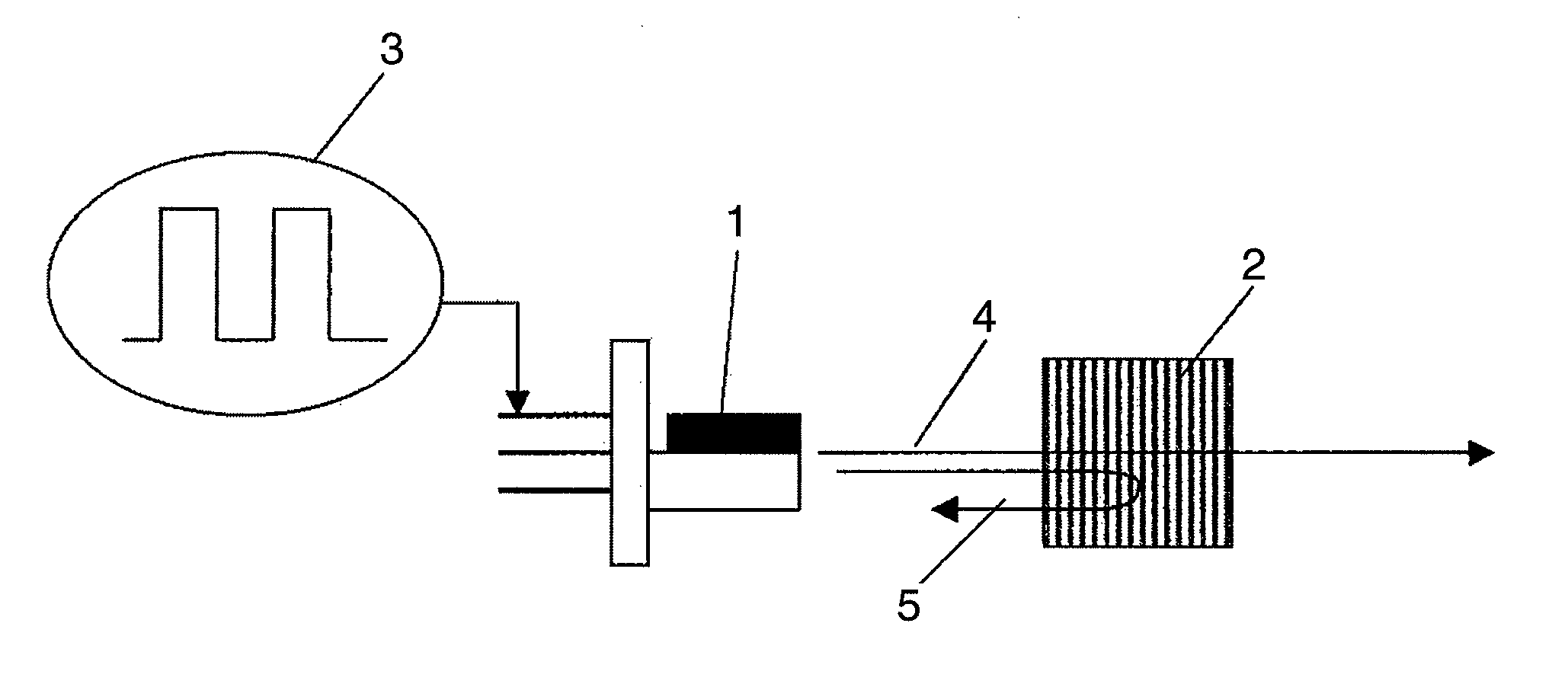
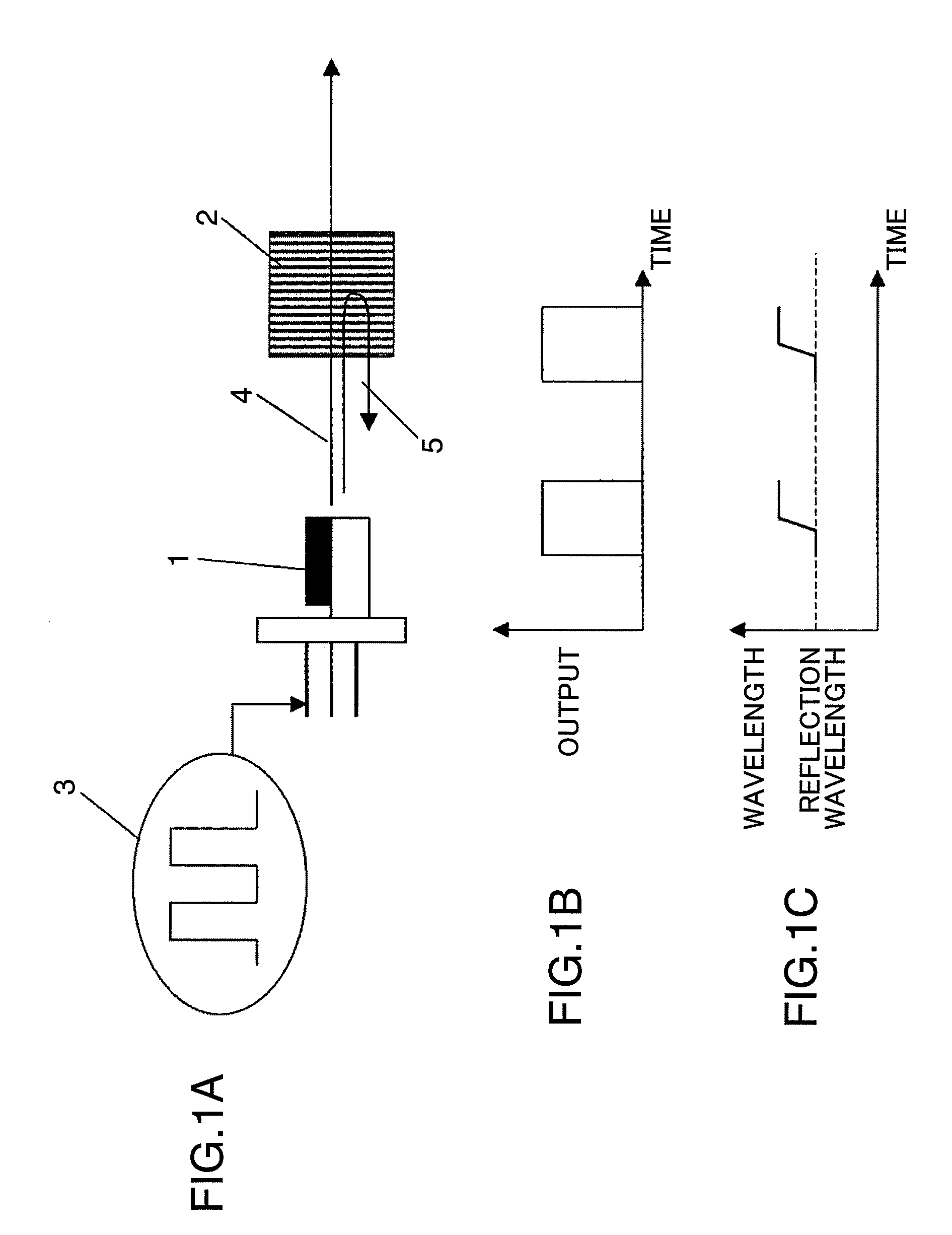
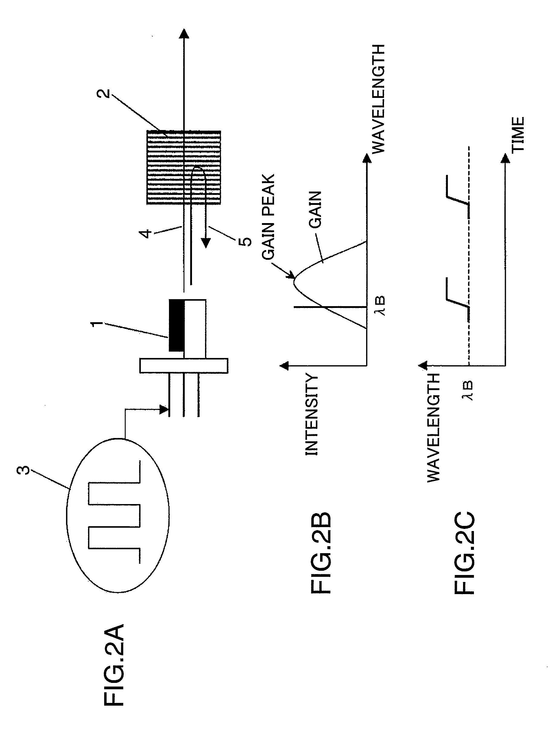
[0013]In the above illumination light source, an oscillating light of the laser light source is fixed at the wavelength of the reflector by reflecting and feeding the part of the laser light emitted from the laser light source back to the laser light source using the reflector. By changing the oscillation characteristic of the laser light source, the peak of the gain region of the laser light source is shifted from the fixed reflection wavelength. Thus, the oscillation spectral width of the laser light source spreads to reduce coherence since the oscillation wavelength of the laser light source can be largely changed. Therefore, an illumination light source with little speckle noise can be realized.

Problems solved by technology

What is problematic in the case of utilizing a visible light semiconductor laser as an illumination light source for a projection device, a display device or the like is speckle noise.
A glaring speckle pattern is observed in the reflected light, which causes the image degradation of the projection device and the display device.
However, the above first method for spatially changing the laser light requires a mechanical driving system in the optical system and has a problem of enlarging and complicating the optical system.
Further, it is difficult to completely suppress the speckle noise only by giving the spatial variation.
On the other hand, the above second method for multimoding the spectrum of the semiconductor laser is effective in reducing the coherence, but no sufficient coherence reducing effect can be obtained unless the spectral width is increased to 1 nm or larger.
Only by superimposing the high frequency wave on the drive of the semiconductor laser, there has been a problem that an increase of the spectral width and a speckle noise reducing effect are insufficient.

Method used


Image

  • Illumination light source device and laser projection device
  • Illumination light source device and laser projection device
  • Illumination light source device and laser projection device

Examples


first embodiment

[0033]FIG. 1A is a diagram showing a construction of an illumination light source according to a first embodiment of the present invention. In FIG. 1A, the illumination light source according to this embodiment is provided with a semiconductor laser 1 as a light source and a reflector 2 for reflecting a part of an emitted light 4 from the semiconductor laser 1 as a basic construction. The emitted light 4 from the semiconductor laser 1 has a part thereof with a specific wavelength reflected by the reflector 2 having a narrow band reflection characteristic, and a reflected light 5 is incident on an active layer of the semiconductor laser 1. An oscillation wavelength of the semiconductor laser 1 is fixed to a reflection wavelength by an optical feedback of the reflected light 5 returned to the active layer. This semiconductor laser 1 is pulse-driven by a driving power supply 3. An output at this time is shown in FIG. 1B. As shown in FIG. 1B, the output of the semiconductor laser 1 is i...

second embodiment

[0075]Next, a second embodiment of the present invention is described. In the first embodiment, a laser light emitted from the semiconductor laser is directly utilized as the illumination light source of the projection device or the display device. On the contrary, in this embodiment, a laser light emitted from a solid-state laser medium by exciting the solid-state laser medium with a laser light from a semiconductor laser is utilized as an illumination light source.

[0076]FIG. 12 shows a construction of the illumination light source according to this embodiment. The illumination light source shown in FIG. 12 is provided with a semiconductor laser 1, a reflector 121, a solid-state laser 122, a nonlinear optical element 123 and mirrors 124, 125. The semiconductor laser 1 is a pumping light source having a wavelength of 808 nm, and a light emitted from the semiconductor laser 1 excites the solid-state laser 122 to produce a laser oscillation. An emitted light 4 from the solid-state las...

third embodiment

[0082]Next, a third embodiment of the present invention is described. In this embodiment, a drive current is modulated to largely vary an oscillation spectrum of a semiconductor laser by superimposing a high frequency wave on a drive current to be applied to the semiconductor laser.

[0083]FIGS. 13A and 13B are graphs showing a method for driving a semiconductor laser of an illumination light source according to this embodiment, wherein FIG. 13A shows the waveform of a current, in which a high frequency wave is superimposed on a drive current for the semiconductor laser wavelength-locked by optical feedback, and FIG. 13B shows the oscillation spectrum of the semiconductor laser, to which a drive current with the current waveform of FIG. 13A is applied. In FIGS. 13A and 13B, “on” indicates a period during which the high frequency wave is superimposed on the drive current and “off” indicates a period during which no high frequency wave is superimposed on the drive current.

[0084]The cohe...


PUM


Abstract

An illumination light source is provided with a laser light source having a laser medium with a specified gain region, and a reflector having a narrow band reflection characteristic. A part of a laser light emitted from the laser light source is reflected and fed back by the reflector, so that an oscillation wavelength of the laser light source is fixed at a reflection wavelength. A peak of a gain region of the laser medium is shifted from the reflection wavelength by a change of an oscillation characteristic of the laser light source, so that the oscillation wavelength of the laser light source is changed from the reflection wavelength. Thus, an oscillation spectrum of the laser light source is spread to reduce speckle noise.

Description

BACKGROUND OF THE INVENTION[0001]1. Field of Invention[0002]The present invention relates to an illumination light source with little speckle noise and a laser projection device using such an illumination light source.[0003]2. Description of the Related Art[0004]Semiconductor lasers made of III-V nitride semiconductor materials (AlxGayIn1-x-yN (where 0≦x≦1, 0≦y≦1), such as gallium nitride and red semiconductor lasers made of AlGaAs semiconductor materials or AlGaInP semiconductor materials are key devices for achieving ultra-high density recording by optical disks. Similarly, higher outputs of these visible light semiconductor lasers not only enable high-speed writing of optical disks, but also are essential technology for pioneering new technological fields such as application to laser displays.[0005]What is problematic in the case of utilizing a visible light semiconductor laser as an illumination light source for a projection device, a display device or the like is speckle noise....

Claims


Application Information

Patent Timeline
Patent Type & Authority Patents(United States)
IPC IPC(8): H01S3/10
CPCG02B27/48G03B21/00G03B21/28H01S3/0627H01S3/09415H01S3/109H01S5/06213H04N9/3129H04N9/315H04N9/3155H01S3/094076H01S5/0612H01S5/06256H01S5/06258H01S5/0652H01S5/1096H01S5/1221H01S5/1237H01S5/141H01S5/146G03B21/005H01S5/2036
Inventor MIZUUCHI, KIMINORIYAMAMOTO, KAZUHISA
Owner PANASONIC CORP
Why Eureka
Eureka Blog
Learn More