Loudspeaker

a loudspeaker and speaker technology, applied in the field of loudspeakers, can solve problems such as deterioration of playback sound quality, and achieve the effects of excellent playback sound quality, small peak dip in sound pressure frequency characteristics, and high adhesive strength

Inactive Publication Date: 2010-11-16
ONKYO TECH KK
View PDF19 Cites 12 Cited by
  • Summary
  • Abstract
  • Description
  • Claims
  • Application Information

AI Technical Summary

Benefits of technology

[0018]The base material of the dome diaphragm preferably contains one of woven fabric and nonwoven fabric made of fibers, and formed by hardening the thermosetting resin that is an unsaturated polyester resin. Because the dome diaphragm is provided with a plurality of cone-shaped projections projecting from the back surface side, and disposed in a circular pattern with a space between each other, the plurality of cone-shaped projections formed by hardening the thermosetting resin define a coupling portion to which the one end of the bobbin is coupled. The dome diaphragm and the bobbin of the voice coil are coupled with adhesive. As a result, the outer circumference end portion of the dome diaphragm is coupled to the outer circumference side end portion of the cone diaphragm, and the one end of the bobbin is coupled to the back surface of the inner circumference side. Accordingly, even with a thin and light weighted dome diaphragm, the dome diaphragm and the cone diaphragm including a paper material formed by papermaking form a rigid vibration system having a high adhesive strength with the bobbin of the voice coil. Thus, it is possible to realize a loudspeaker whose playback sound quality is excellent with a small peak dip in sound pressure frequency characteristics.
[0019]The height of each of the plurality of cone-shaped projections is set greater than a sum of maximum values of absolute values respectively of height tolerance of the dome diaphragm, height tolerance of the cone diaphragm, and height tolerance of the bobbin of the voice coil, and a cone radius defining each cone-shaped projection is set greater than a maximum value of an absolute value of radius tolerance of the bobbin. Specifically, in the loudspeaker according to the present invention, the coupling portion to which the one end of the bobbin is constituted by the plurality of cone-shaped projections defined in consideration of the dimensional and assembly tolerance of the components to which the bobbin of the voice coil is attached. Therefore, a loudspeaker vibration system can be stably produced such that the outer circumference end portion of the cone diaphragm is coupled closely to the dome diaphragm, and the bobbin of the voice coil is coupled closely to the dome diaphragm. As a result, with the loudspeaker according to the present invention, it is possible to reduce the possibility of occurrence of the problems that the back surface side of the dome diaphragm and the bobbin of the voice coil are spaced apart, that the outer circumference end portion of the dome diaphragm and the outer circumference end portion of the cone diaphragm are spaced apart, or that the dome diaphragm or the cone diaphragm is coupled in a deformed state with a stress being applied.
[0020]Further, in the vibration system of the loudspeaker according to the present invention, the cone diaphragm is further provided with a plurality of through holes in the vicinity of the inner circumference end portion of the cone diaphragm, and therefore a space formed by closely coupling the dome diaphragm, the cone diaphragm, and the bobbin of the voice coil is not hermetically sealed. Accordingly, a solvent contained in the applied adhesive may not be confined in this space and the adhesive can be strongly hardened, thereby eliminating problems of deformation of the vibration system due to the presence of the solvent, and of the adhesive coming into the magnetic gap of the magnetic circuit when assembling the diaphragm. Thus, it is possible to stably provide a loudspeaker having excellent playback sound quality.

Problems solved by technology

As can be seen from the description “workability is improved” in the same paragraph, this is due to the fact that it is extremely difficult, for a loudspeaker designed such that a cone diaphragm and a bobbin of a voice coil are both coupled to a dome diaphragm, to produce stable loudspeakers in which an end of the outer circumference of the cone diaphragm is closely coupled to the dome diaphragm, and the bobbin of the voice coil is closely coupled to the dome diaphragm because the production is affected by dimensional tolerance and assembly tolerance of components for the dome diaphragm, the cone diaphragm, and the bobbin of the voice coil.
Specifically, in the production of a loudspeaker having a dome diaphragm and a cone diaphragm, due to variations in the tolerance for components, there can be such problems in which a back side of the dome diaphragm and the bobbin of the voice coil are spaced apart, the end of the outer circumference of the dome diaphragm and the end of the outer circumference of the cone diaphragm are spaced apart, and either the dome diaphragm or the cone diaphragm is deformed and the diaphragms are coupled with a stress being applied therebetween.
This disadvantageously hinders stable production of loudspeakers, resulting in deterioration of playback sound quality.

Method used


Image

  • Loudspeaker
  • Loudspeaker
  • Loudspeaker

Examples


embodiment 1

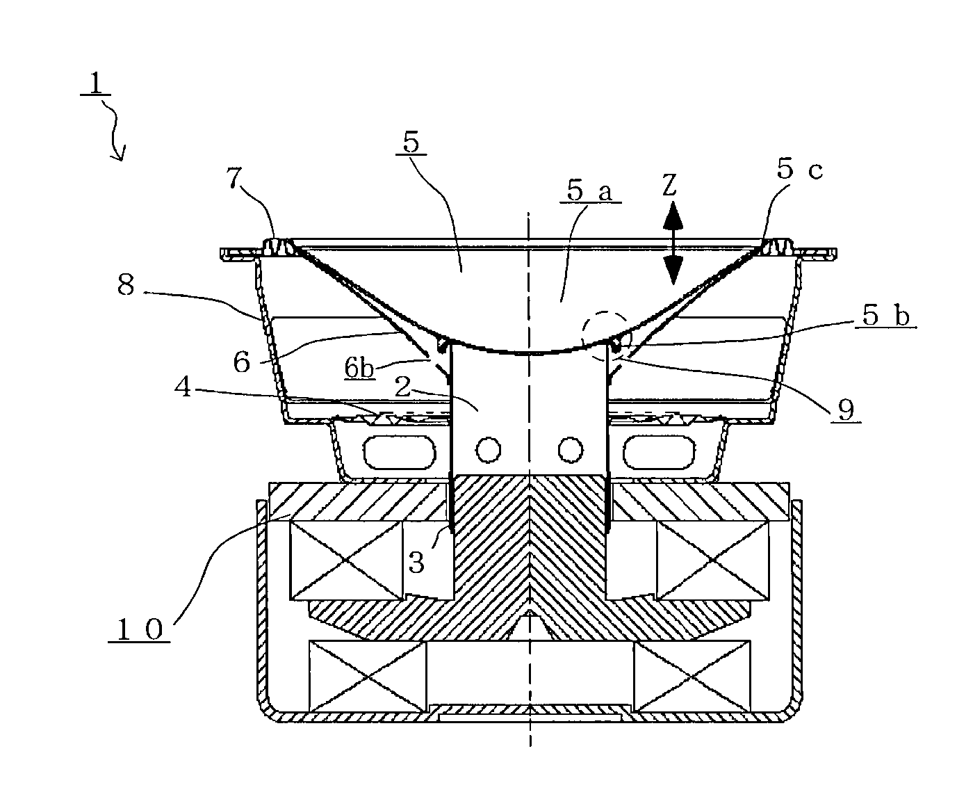
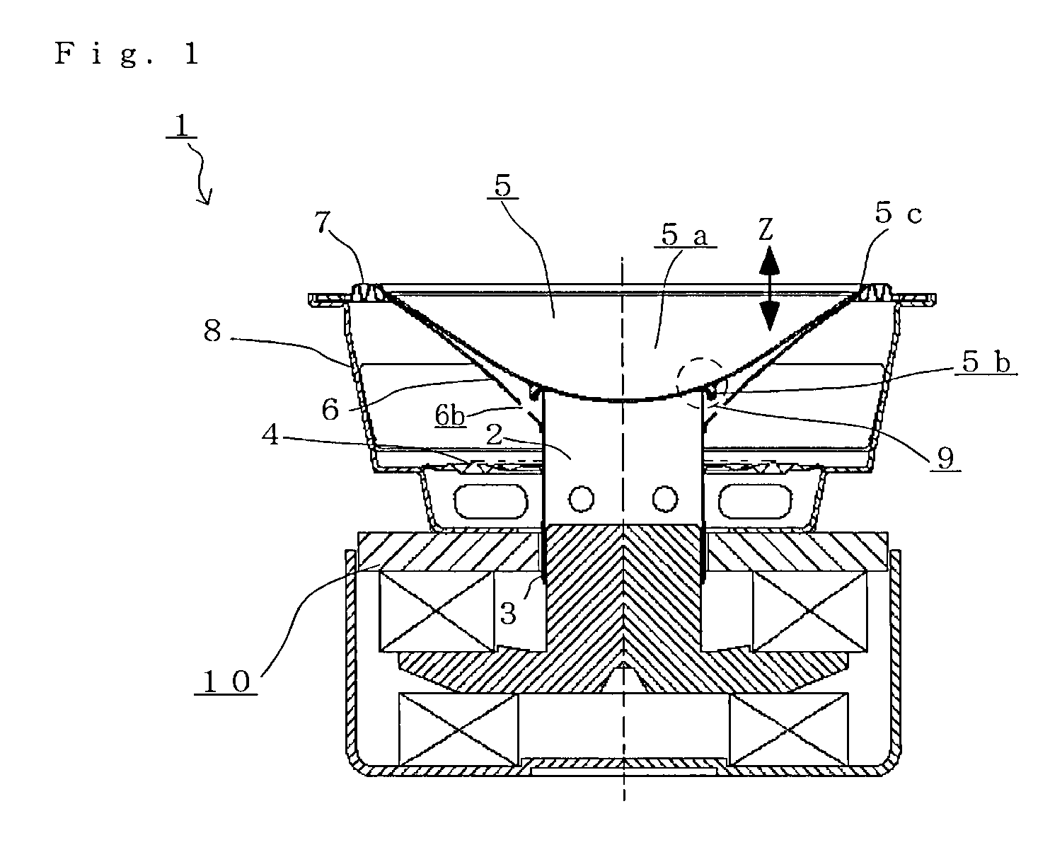
[0028]FIG. 1 is a schematic cross-sectional view of a loudspeaker 1 according to a preferred embodiment of the present invention. The loudspeaker 1 is an electrodynamic loudspeaker with an aperture diameter of 8 cm, and includes a dome diaphragm 5, a cone diaphragm 6 whose outer circumference side end portion is coupled to an outer circumference end portion of the dome diaphragm 5, a voice coil bobbin 2 whose one end is coupled to a back surface of the dome diaphragm 5 and whose outer curved surface is coupled with an inner circumference end portion of the cone diaphragm 6, and a voice coil 3 that is wound about a lower end portion of the voice coil bobbin 2. The voice coil 3 is provided in a magnetic gap of a magnetic circuit 10, and drives a vibration system of the loudspeaker 1 in response to an input signal by being displaced within the magnetic gap. The vibration system constituted by the dome diaphragm 5, the cone diaphragm 6, and the voice coil bobbin 2 is vibratably supporte...

embodiment 2

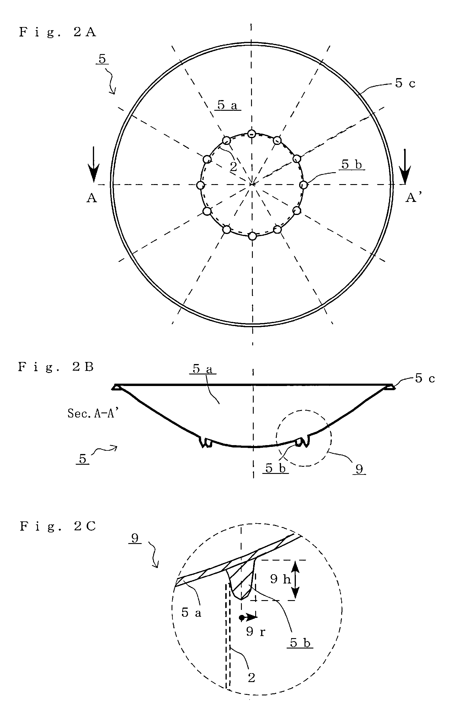
[0050]FIGS. 6A and 6B are diagrams illustrating dome diaphragms 51 and 52 each constituting a loudspeaker (not shown) of a different embodiment according to the present invention. This embodiment is substantially the same as the previously described embodiment 1, other than that an arrangement of the plurality of cone-shaped projections 5b defining the coupling portion 9 between the dome diaphragm 5 and the voice coil bobbin 2 is different. Accordingly, the like components are designated by the same numerals and descriptions for these components are not repeated. FIG. 6A is a plan view of the dome diaphragm 51 viewed from the back surface side, and FIG. 6B is a plan view of the dome diaphragm 52 viewed from the back surface side.

[0051]As shown in FIG. 6A, a coupling portion 91 of the dome diaphragm 51 that constitutes the loudspeaker of the different embodiment is defined by the plurality of cone-shaped projections 5b that are disposed in a circular pattern with a space between each...


PUM


Abstract

The loudspeaker includes a dome diaphragm that is made of a base material impregnated in a thermosetting resin; a cone diaphragm whose outer circumference side end portion is coupled with an outer circumference end portion of the dome diaphragm; and a voice coil having a bobbin whose one end is coupled to a back surface of the dome diaphragm, and whose outer curved surface is coupled with an inner circumference end portion of the cone diaphragm, wherein the dome diaphragm is provided with a plurality of cone-shaped projections that is formed by hardening the thermosetting resin, projecting from the back surface, and disposed in a circular pattern with a space between each other, the plurality of cone-shaped projections defining a coupling portion to which the one end of the bobbin is coupled.

Description

BACKGROUND OF THE INVENTION[0001]1. Field of the Invention[0002]The present invention relates to loudspeakers that utilize a diaphragm having high joining strength to a voice coil bobbin, and more specifically to a loudspeaker in which a dome diaphragm made of a base material impregnated in a thermosetting resin is exposed to a front side, and a cone diaphragm and a voice coil bobbin are both coupled to the dome diaphragm.[0003]2. Description of the Related Art[0004]In many cases, loudspeakers employ an assembly structure in which an end of an inner circumference of a loudspeaker diaphragm (especially, cone-shaped diaphragm) is joined with adhesive to a side wall of a cylindrical voice coil bobbin. In some conventional loudspeakers, various efforts are made to the assembly structure in order to reduce the number of assembling steps. Further, as adhesive strength between a voice coil bobbin and a loudspeaker diaphragm in a loudspeaker affects characteristics of sound to be played, va...

Claims


Application Information

Patent Timeline
Patent Type & Authority Patents(United States)
IPC IPC(8): H04R25/00
CPCH04R9/045H04R7/127H04R9/063H04R2207/021H04R2307/029H04R2499/13
Inventor INOUE, TAKERUSEKIYA, MAMORU
Owner ONKYO TECH KK
Why Eureka
Try Eureka