
Aircraft combination engines thermal management system

a technology for thermal management system and aircraft, applied in the direction of machines/engines, turbine/propulsion fuel heating, lighting and heating apparatus, etc., can solve the problems of large electrical power demand peaks repeatedly, the fuel use efficiency of aircraft during flight is relatively low, and the electrical power demand of military aircraft is often high

Inactive Publication Date: 2010-11-23
RAYTHEON TECH CORP
View PDF7 Cites 58 Cited by
  • Summary
  • Abstract
  • Description
  • Claims
  • Application Information

AI Technical Summary

Benefits of technology

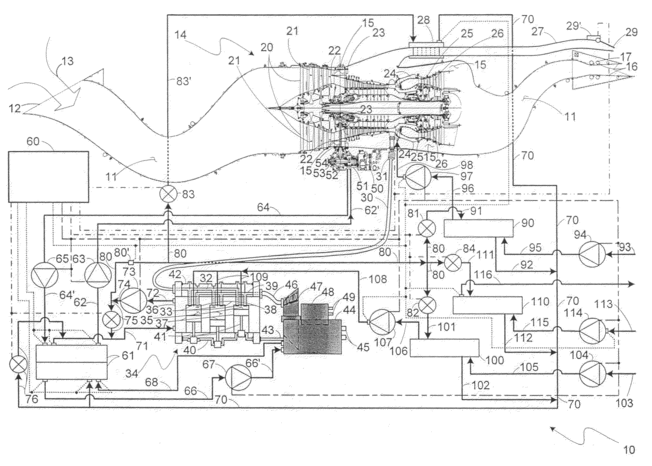
"The present invention provides an engine combination that generates forces using a gas turbine engine and an intermittent combustion engine. The air compressor of the gas turbine engine receives compressed air through an air transfer duct, while the intermittent combustion engine generates force through its output shaft. The coolant is used to transport heat away from both engines, and a coupling heat exchanger is used to cool the engine lubricant and the coolant. A further cooling heat exchanger is used to cool the remote fluid. The primary electrical generator is connected to the output shaft of the intermittent combustion engine and is cooled by the coolant. The technical effect of this invention is the efficient cooling of moving components in the gas turbine engine and the intermittent combustion engine, which leads to improved performance and durability."

Problems solved by technology

Furthermore, such demands for electrical power in military aircraft often occur at relatively high altitudes and often occur unevenly over relatively long time durations of use, that is, large peaks repeatedly occur in electrical power demand in the course of those long use durations.
Making up that thrust loss in these circumstances by operating such available turbine engines so as to increase the thrust output thereof causes the already relatively low fuel use efficiency during flight to decrease significantly, which can severely limit the length of otherwise long duration uses, and also brings those engines closer to becoming operationally unstable.
At high altitudes, internal combustion engines of all kinds face the possibility of limited power output because of the relatively small air pressures there limiting the chemical reactions of oxygen with hydrogen and oxygen with carbon in the burning of the engine fuel in the engine combustion chamber or chambers.
However, the small density and pressure of the air there also makes it difficult to use that air to provide sufficient cooling for the lubricants used for in each of the gas turbine and intermittent combustion engines, the heat generated in such lubricants in any event being wasted by such air cooling in having that heat lost to the atmosphere.

Method used


Image

  • Aircraft combination engines thermal management system
  • Aircraft combination engines thermal management system
  • Aircraft combination engines thermal management system

Examples


Embodiment Construction

[0014]Keeping heat in operating internal combustion engines of all kinds that has been generated in those engines during such operation thereof increases the thermodynamic efficiency of those operations. Of course, there are limits to operating those engines with such a goal that are imposed by the maximum temperatures that various engine components can withstand before failing in some manner. These limits are avoided typically by providing suitable cooling arrangements of some sort for the engines, and sometimes their loads devices, but such cooling should not be overdone as this cooling requires using energy therefor that is typically supplied from the engines being cooled. Such energy use thereby reduces the energy from the engines that would otherwise be available for propulsion or such other tasks that have been assigned to the engine. That is, the engines and their loads should be operated at their maximum feasible operating temperatures for reasons of efficiency.

[0015]In an a...


PUM


Abstract

An engine combination for generating forces with a gas turbine engine generating force that utilizes an engine lubricant for lubricating moving components in the turbofan engine, and an internal combustion engine provided in the combination as an intermittent combustion engine generating force that utilizes a coolant for transporting heat generated in the intermittent combustion engine away therefrom and having an air intake, there being an air transfer duct connected from a compressor in the gas turbine engine to the air intake to transfer compressed air thereto. A coupling heat exchanger is coupled to both the gas turbine engine and the intermittent combustion engine to have the engine lubricant and the coolant pass therethrough. A further cooling heat exchanger is coupled to both the coupling heat exchanger and the intermittent combustion engine to have a remote fluid from a source thereof and the coolant pass therethrough.

Description

CROSS-REFERENCE TO RELATED APPLICATION[0001]Referenced herein is U.S. application Ser. No. 11 / 713,262 filed Mar. 2, 2007 for “COMBINATION ENGINES FOR AIRCRAFT” by Frederick M. Schwarz, Brian M. Fentress, Andrew P. Berryann, Charles E. Lents and Jorn A. Glahn.BACKGROUND OF THE INVENTION[0002]The present invention relates to gas turbine engines for aircraft and, more particularly, to gas turbine engines each coupled to a corresponding auxiliary engine.[0003]Gas turbine engines as continuous combustion, open Brayton cycle internal combustion engines have come to dominate as the power plants for larger, faster aircraft to essentially the exclusion of reciprocating engines, or internal, intermittent combustion engines, earlier used as power plants for these kinds of aircraft. This is largely because of the greater power-to-weight ratio of gas turbine engines versus internal combustion engines, especially in large horsepower engines, or, more appropriately, large thrust engines in which t...

Claims


Application Information

Patent Timeline
Patent Type & Authority Patents(United States)
IPC IPC(8): F02K3/00
CPCF01D15/10F01D13/02F01D25/125F02K3/06F02K3/115F02C6/08F02C6/10F02C7/185F02C7/224Y02T50/676F05D2220/76F05D2260/213Y02T50/60
Inventor SCHWARZ, FREDERICK M.GLAHN, JORN A.FENTRESS, BRIAN M.
Owner RAYTHEON TECH CORP
Learn More