
Combustion optimization for fossil fuel fired boilers

Active Publication Date: 2010-11-23
GENERAL ELECTRIC CO
View PDF38 Cites 16 Cited by
  • Summary
  • Abstract
  • Description
  • Claims
  • Application Information

AI Technical Summary

Benefits of technology

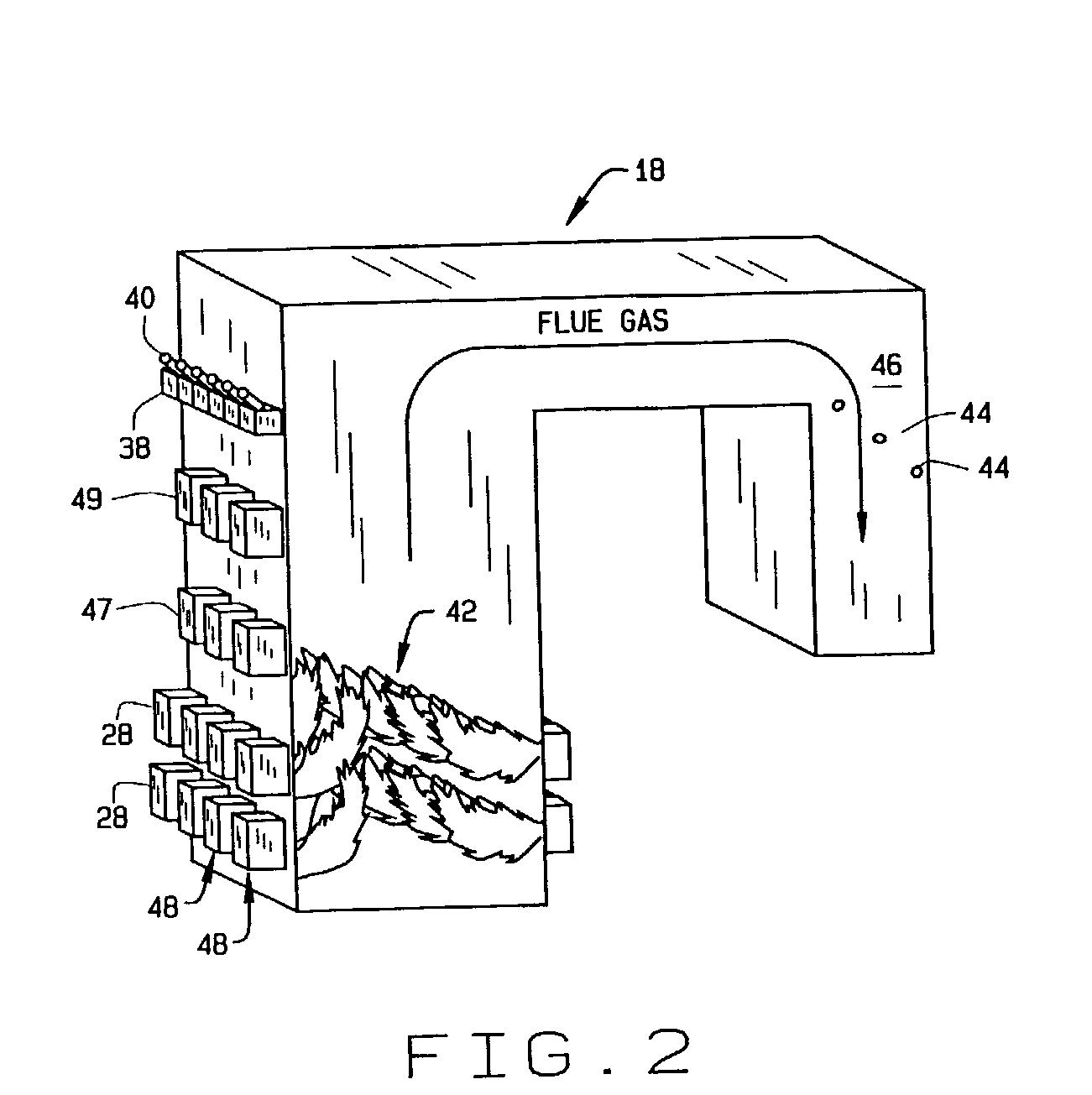
[0007]In one aspect, a method of optimizing operation of a fossil fuel fired boiler is provided. The boiler includes a plurality of burners with each burner receiving fossil fuel and combustion air. The method includes providing a plurality of sensors positioned in different spatial positions within the fossil fuel fired boiler. The method also includes recording sensor outputs, identifying spatial combustion anomalies indicated by sensor outputs, identifying burners responsible for the spatial combustion anomalies, and adjusting air flow of responsible burners to alleviate the spatial combustion anomalies.

Problems solved by technology

Some emissions, such as the concentration of unburned carbon in fly ash and Hg are difficult to monitor on-line and continuously.
Measurement of the aggregate emissions, or measurement of emissions on a periodic or occasional basis, however, do not provide an indication of what combustor parameters should be changed and / or which combustor zone should be adjusted.
The absence of effective methods to adequately monitor and control the coal and air flows can contribute to a boiler not operating under its optimal combustion conditions.
As a result of the operation under high excess air there can be an increase in NOx emissions and a reduction in the boiler's efficiency which increases operational costs for fuel and NOx credits and reduces output due to emissions caps.
In these applications, burner imbalance can have an impact on gas temperature uniformity.
These peak temperatures caused by fuel-rich burners can lead to increased metal fatigue, slagging (melted ash) deposits on convective passes, corrosive gases and high ash loadings in local convective pass regions.
Sootblowing, high temperature gases and corrosive gases lead to deterioration of watertube and waterwall metals resulting in frequent forced outages with lost power generation capability.

Method used


Image

  • Combustion optimization for fossil fuel fired boilers
  • Combustion optimization for fossil fuel fired boilers
  • Combustion optimization for fossil fuel fired boilers

Examples


Embodiment Construction

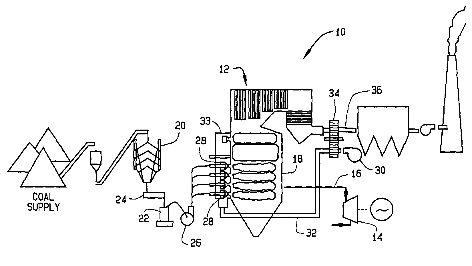
[0013]A method of optimizing operation of a fossil fuel fired boiler is described below in detail. The method includes the use of a plurality of different sensors in different spatial locations within a particulate fossil fuel fired boiler furnace to track in-furnace combustion conditions and the relative differences between individual burners. The method also includes using the sensor information to make adjustments to individual burners to yield an optimized boiler performance. The optimized operating burner conditions can vary from one burner to another. This means that the air flow and fuel flow can vary from burner to burner and that the air to fuel ratio to individual burners are not predetermined. Rather, each burner is biased and adjusted to meet boiler performance objectives as indicated by the in-furnace sensors. Optimized performance includes, for example, reduced NOx emissions, reduced LOI emissions, increased efficiency, increased power output, improved superheat temper...


PUM


Abstract

A method of optimizing operation of a fossil fuel fired boiler includes, in an exemplary embodiment, providing a plurality of sensors positioned in different spatial positions within the fossil fuel fired boiler. The method also includes recording sensor outputs, identifying spatial combustion anomalies indicated by sensor outputs, identifying burners responsible for the spatial combustion anomalies, and adjusting air flow of responsible burners to alleviate the spatial combustion anomalies.

Description

BACKGROUND OF INVENTION[0001]This invention relates generally to boilers, and more particularly to the optimization of combustion in fossil fuel fired boilers.[0002]In numerous industrial environments, a hydrocarbon fuel is burned in stationary combustors (e.g., boilers or furnaces) to produce heat to raise the temperature of a fluid, e.g., water. For example, the water is heated to generate steam, and this steam is then used to drive turbine generators that output electrical power. Such industrial combustors typically employ an array of many individual burner elements to combust the fuel. In addition, various means of combustion control, such as overfire air, staging air, reburning systems, selective non-catalytic reduction systems, can be employed to enhance combustion conditions and reduce oxides of nitrogen (NOx) emission.[0003]For a combustor to operate efficiently and to produce an acceptably complete combustion that generates byproducts falling within the limits imposed by en...

Claims


Application Information

Patent Timeline
IPC IPC(8): G01N33/00F23N1/02F23N3/04F23N5/00
CPCF23N1/022F23N3/042F23N5/003Y10T436/12F23N2021/00F23N2021/10F23N5/006F23N2221/00F23N2221/10
Inventor WIDMER, NEIL COLINPAYNE, ROYSEEKER, WILLIAM RANDALLGAUTHIER, PHILIPPE JEAN
Owner GENERAL ELECTRIC CO
Learn More