Method and apparatus for dehumidification

a dehumidification and apparatus technology, applied in the field of dehumidification methods and apparatuses, can solve the problems of overcooling, overcooling is a particular problem, overcooling, etc., and achieve the effects of enhancing dehumidification features, reheating air, and convenient retrofitting

Active Publication Date: 2010-12-07
JOHNSON CONTROLS TYCO IP HLDG LLP
View PDF177 Cites 32 Cited by
  • Summary
  • Abstract
  • Description
  • Claims
  • Application Information

AI Technical Summary

Benefits of technology

[0010]One advantage of the present invention is that it may easily be retrofitted into existing systems.
[0011]Another advantage of the present invention is that the system and method distributes refrigerant substantially uniformly across the evaporator to provide substantially uniform refrigerant phase distribution and heat exchange across the evaporator.
[0012]Another advantage of the present invention is that the system can reheat air without the need for a separate airflow system.
[0013]Another advantage of the present invention is that the system does not require a discrete reheat coil.
[0014]Another advantage of this system is that enhanced dehumidification features are made available without increasing energy usage associated with circulating indoor air.

Problems solved by technology

One drawback to using an evaporator, alone, for dehumidification, is the excess reduction in air temperature that results, which is commonly referred to as overcooling.
Overcooling is a particular problem when the dehumidification is required in a room that is already relatively cool.
The reheat coil system for providing heat to the dehumidified, overcooled air has several drawbacks including the requirement of additional equipment and / or piping and / or additional energy input.
The presence of an additional coil in the indoor air stream results in losses that must be overcome by the indoor blower.
These losses are present any time the indoor blower is running, regardless of the operational mode of the unit.
One drawback of the '133 system is that the dehumidified air is not reheated and may be overcooled.
Another drawback of the '133 system is that the inlet header does not distribute flow across the circuits of the evaporator, leading to uneven phase distribution of refrigerant across the evaporator heat exchanger.

Method used


Image

  • Method and apparatus for dehumidification
  • Method and apparatus for dehumidification
  • Method and apparatus for dehumidification

Examples


Embodiment Construction

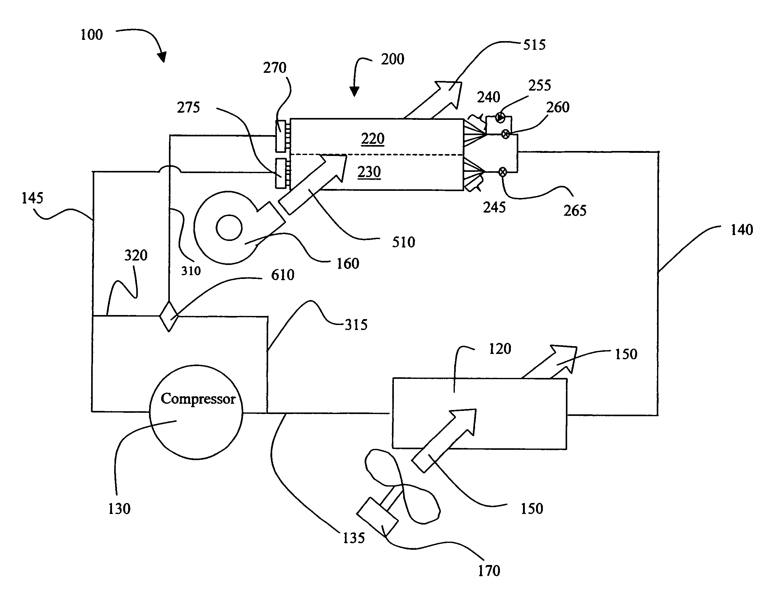
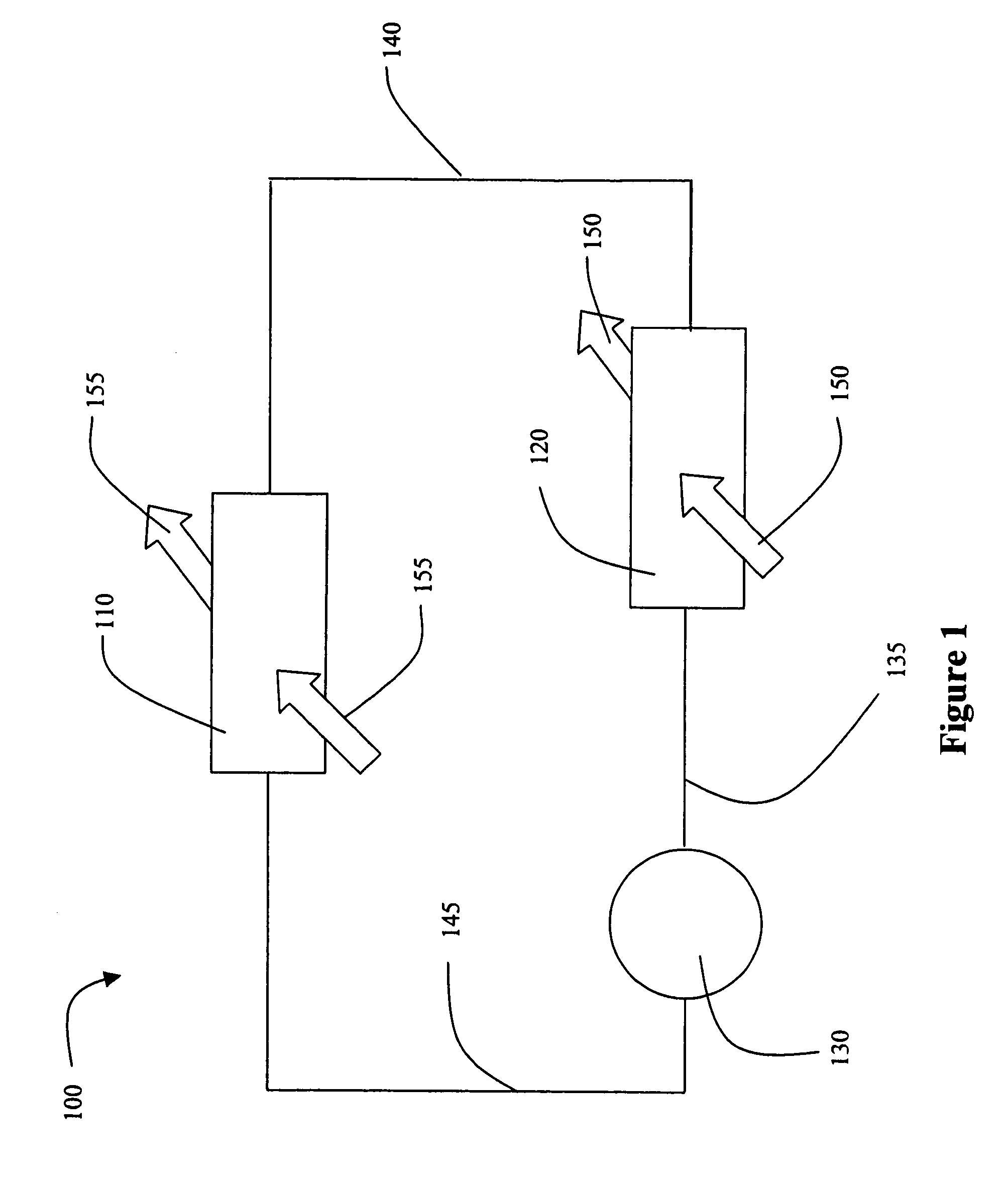
[0030]FIG. 1 illustrates a HVAC, refrigeration, or chiller refrigeration system 100. Refrigeration system 100 includes a compressor 130, a condenser 120, and an evaporator 110. Refrigerant is circulated through the refrigeration system 100. The compressor 130 compresses a refrigerant vapor and delivers it to the condenser 120 through compressor discharge line 135. The compressor 130 is preferably a reciprocating or scroll compressor, however, any other suitable type of compressor can be used, for example, screw compressor, rotary compressor, and centrifugal compressor. The refrigerant vapor delivered by the compressor 130 to the condenser 120 enters into a heat exchange relationship with a first heat transfer fluid 150 heating the fluid while undergoing a phase change to a refrigerant liquid as a result of the heat exchange relationship with the fluid 150. The first heat transfer fluid 150 is moved by use of a fan 170 (see FIG. 5), which moves the first heat transfer fluid 150 throu...


PUM


Abstract

An HVAC system including a compressor, a condenser and an evaporator arrangement connected in a closed refrigerant loop. The evaporator arrangement includes a plurality of refrigerant circuits. The evaporator arrangement also includes at least one distributor configured to distribute and deliver refrigerant to each circuit of the plurality of circuits. The plurality of circuits are arranged into a first and second set of circuits. The evaporator arrangement also includes a valve configured and disposed to isolate the first set of circuits from refrigerant flow from the condenser and provide flow of refrigerant from the compressor in a dehumidification operation of the HVAC system.

Description

CROSS-REFERENCE TO RELATED APPLICATIONS[0001]This application claims the benefit of U.S. Provisional Application No. 60 / 640,038 filed Dec. 29, 2004.FIELD OF THE INVENTION[0002]The present invention is directed to providing dehumidification in heating, ventilation and air conditioner (HVAC) systems. In particular, the present invention is directed to an arrangement for HVAC systems that can dehumidify air.BACKGROUND OF THE INVENTION[0003]Dehumidification of air in HVAC systems typically takes place through the use of the evaporator in cooling mode. One drawback to using an evaporator, alone, for dehumidification, is the excess reduction in air temperature that results, which is commonly referred to as overcooling. Overcooling occurs when air that is subject to dehumidification is cooled to a temperature that is below the desired temperature of the air. Overcooling is a particular problem when the dehumidification is required in a room that is already relatively cool. Overcooling gene...

Claims


Application Information

Patent Timeline
Patent Type & Authority Patents(United States)
IPC IPC(8): F25B41/00
CPCF24F3/153F25B5/02F25B2400/0403F25B2600/2507
Inventor KNIGHT, JOHN TERRYLANDERS, ANTHONY WILLIAMGAVULA, PATRICK GORDONPICKLE, STEPHEN BLAKE
Owner JOHNSON CONTROLS TYCO IP HLDG LLP
Why Eureka
Try Eureka