Plug connector with two rows of soldering sections

Active Publication Date: 2010-12-14
ADVANCED CONNECTEK INC
View PDF4 Cites 40 Cited by
  • Summary
  • Abstract
  • Description
  • Claims
  • Application Information

AI Technical Summary

Benefits of technology

[0007]The main objective of the invention is to provide a plug connector that has two rows of soldering sections of terminals to re

Problems solved by technology

However, USB 2.0 protocol only allows a maximum transmission speed of 480 Mbps.
Because electronic devices are constantly developed to increase transmission speeds, the USB 2.0 protocol does not meet current transmission speed requirement of new electronic devices.
However, a USB 3.0 connector h

Method used


Image

  • Plug connector with two rows of soldering sections
  • Plug connector with two rows of soldering sections
  • Plug connector with two rows of soldering sections

Examples


Example

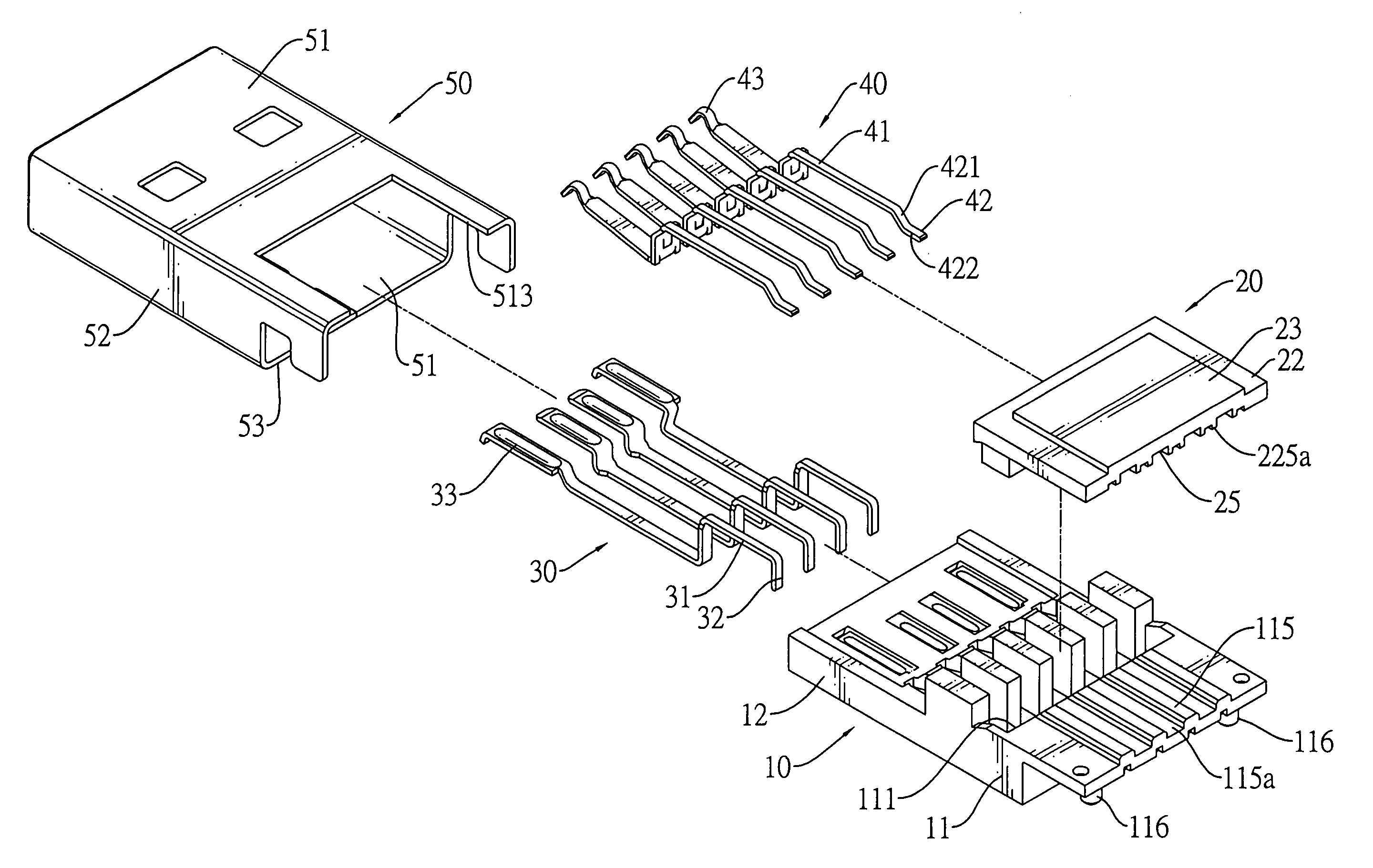
[0042]With further reference to FIG. 6A, a first embodiment of the plug connector in accordance with the present invention has soldering sections (32) of the first terminals (30) being through hole technology (THE) type and straight so that the soldering sections (32) extend through soldering holes of a PCB. The soldering sections (42) of the second terminals (40) are surface mount technology (SMT) type and each soldering section (42) is substantially L-shaped and has an inclined segment (421) and a level segment (42). The inclined segment (421) protrudes obliquely downward from the mounting section (41). The level segment (422) protrudes horizontally backward from the inclined segment (421) and may be soldered on a PCB.

Example

[0043]With reference to FIG. 6B, a second embodiment of the plug connector in accordance with the present invention has the soldering sections (32, 42a) of the first and second terminals (30, 40a) being THE type and straight.

[0044]With further reference to FIG. 9A, a plot of impedance against time shows a curve indicating impedance of the first embodiment of the plug connector of the first embodiment during signal transmission. The unit of impedance is “ohm” and that of the time is “10−12 second (Pico-second, ps)”. As indicated by the curve, when signal transmission is implemented, maximum and minimum impedance values of the first embodiment are 103 and 83 ohm and are within acceptable standards for USB 3.0 plug connectors by having a range of 75 to 105 ohms. Therefore, advantages of the first embodiment of the plug connector include stable high frequency signal transmission.

[0045]With further reference to FIG. 9B, a plot of impedance against time shows a curve indicating impedance ...


PUM


Abstract

A plug connector has an insulative housing, a mounting bracket, multiple first terminals, multiple second terminals and a shell. The mounting bracket is mounted on the insulative housing. The first terminals are mounted through the insulative housing and have soldering sections arranged in a first transverse row. The second terminals are mounted through the mounting bracket and have soldering sections arranged in a second transverse row. The soldering sections arranged in the different rows reduce a density of a soldering section layout and facilitate soldering the plug connector to a PCB.

Description

BACKGROUND OF THE INVENTION[0001]1. Field of the Invention[0002]The present invention relates to a connector, and more particularly to a plug connector that has two rows of soldering sections of terminals to reduce a density of a soldering section layout to facilitate a soldering process and improve a production rate of the plug connector.[0003]2. Description of Related Art[0004]Conventional Universal Serial Bus (USB) 2.0 connectors are popularly used in various electronic devices. However, USB 2.0 protocol only allows a maximum transmission speed of 480 Mbps. Because electronic devices are constantly developed to increase transmission speeds, the USB 2.0 protocol does not meet current transmission speed requirement of new electronic devices. Therefore, the USB Implementers Forum (USB IF) established USB 3.0 protocol, with a theoretical maximum transmission speed of 5 Gbps.[0005]However, a USB 3.0 connector having two rows of terminals is structurally complicated so manufacturing a ...

Claims


Application Information

Patent Timeline
IPC IPC(8): H01R12/00
CPCH01R12/712H01R27/00H01R13/6473H01R23/6873H01R12/57H01R12/58H01R13/658
Inventor WAN, WEIDUAN, SHU-LINCHEN, CHING-TIENHOU, PIN-YUANKO, WEN-CHIH
Owner ADVANCED CONNECTEK INC
Why Eureka
Try Eureka