Integrated design for omni-directional camera and microphone array

a technology of omni-directional cameras and microphone arrays, applied in two-way working systems, television conference systems, television systems, etc., can solve the problems of limited commercial success of video conferencing systems, insufficient image resolution, technical deficiencies, etc., and achieve the effect of enhancing the video and audio data captured

Active Publication Date: 2010-12-14
MICROSOFT TECH LICENSING LLC
View PDF80 Cites 40 Cited by
  • Summary
  • Abstract
  • Description
  • Claims
  • Application Information

AI Technical Summary

Benefits of technology

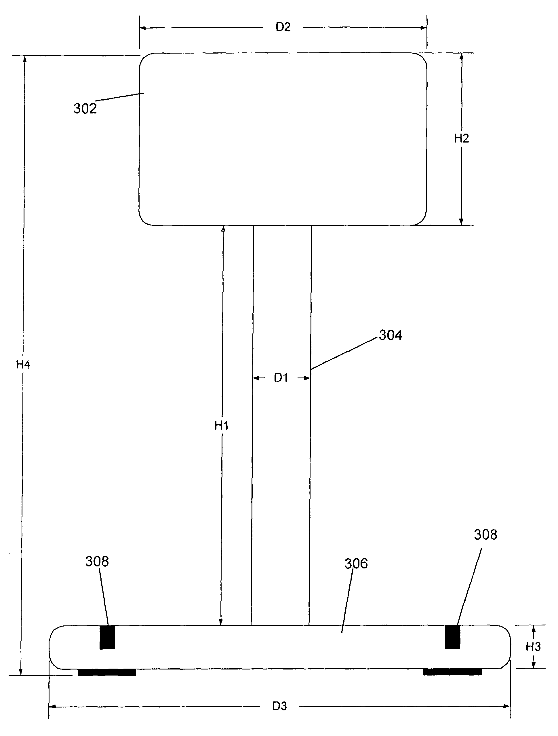
[0011]In the most general sense, the invention consists of a cylindrical rod that is thin enough to be acoustically invisible for the frequency ranges of human speech (50-4000 Hz) and connects a camera array to a microphone array. As a result, sound diffraction and shadowing are eliminated.
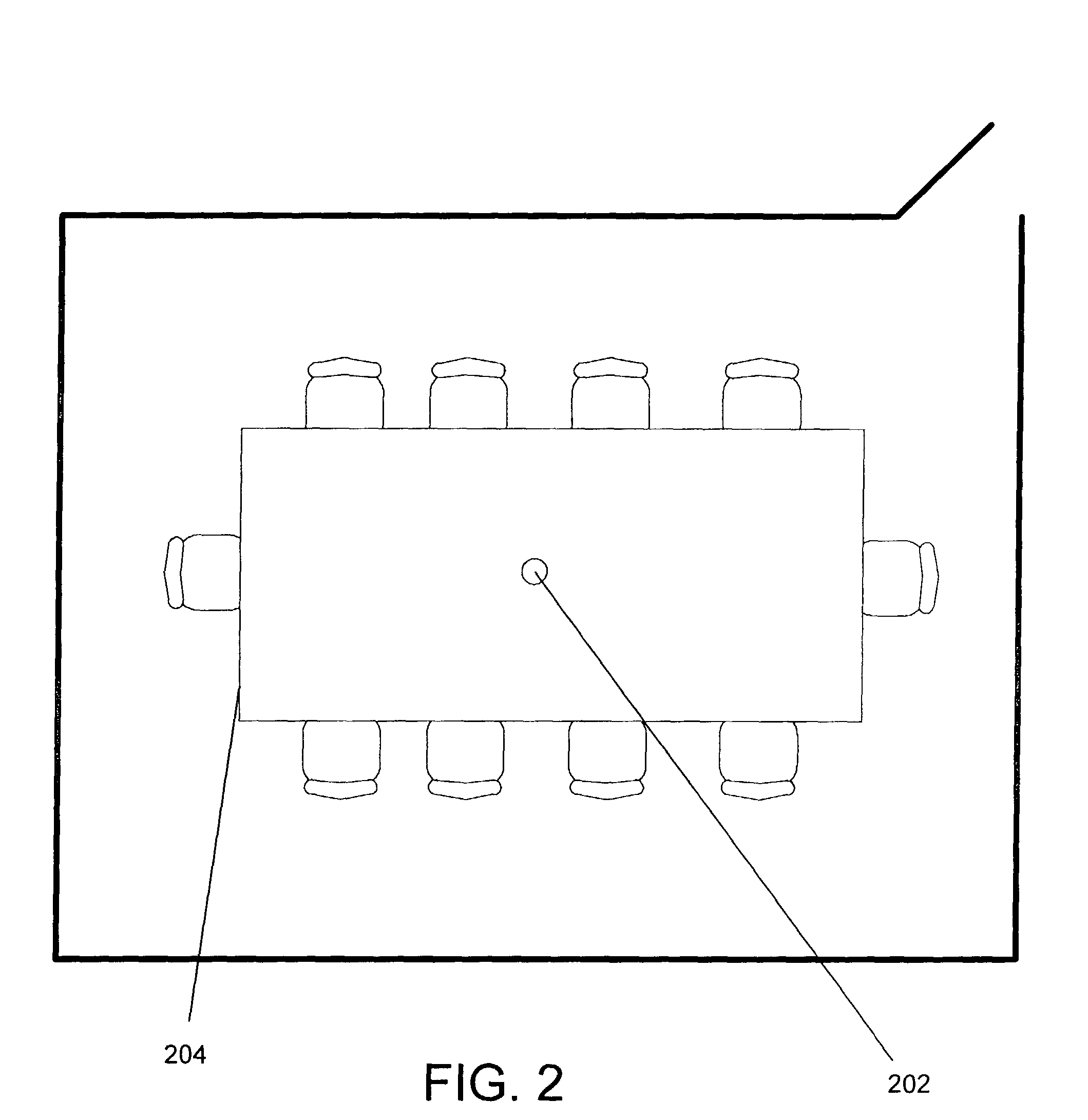
[0023]The primary application for the above-described integrated camera and microphone array is videoconferencing and meeting recording. By integrating the microphone array with the omni-directional camera, the calibration between the video and audio needed is greatly simplified (a precisely manufactured camera and microphone array needs no calibration) and gathering audio and video information from a conference room with a single device is achieved.

Problems solved by technology

Video conferencing systems have had limited commercial success.
In particular, there are typically numerous technical deficiencies in these systems.
Poor camera viewpoints and insufficient image resolution make it difficult for meeting participants to see the person speaking.
This is compounded by inaccurate speaker detection (especially for systems with pan-tilt-zoom cameras) that causes the camera not to be directed at the person speaking.
Additionally, poor video compression techniques often result in poor video image quality and “choppy” image display.
While PTZ cameras are currently the most popular choice, they have two major limitations.
First, they can only capture a limited field of view.
If they zoom in too closely, the context of the meeting room is lost; if they zoom out too far, people's expressions become invisible.
Second, because the controlling motor takes time to move the camera, the camera's response to the meeting (e.g., switching between speakers) is slow.
In fact, PTZ cameras cannot move too much or too fast, otherwise people watching the meeting can be quite distracted.
While this approach overcomes the two difficulties of limited field of view and slow camera response faced by the PTZ cameras, these types of devices tend to be too expensive to build given today's technology and market demand.
In addition, these mirror prism-based omni-directional cameras suffer from low resolution (even with 1 MP sensors) and defocusing problems, which result in inferior video quality.
However, there are disadvantages with this design.
First, NTSC cameras provide a relatively low quality video signal.
The requirement for four video capturing boards increases the cost and complexity of such a system, and makes it more difficult to manufacture and maintain.
Besides the problems noted with video capture, capturing high-quality audio in a meeting room is also challenging.
The simplest approach is to use close-up microphones (e.g., via headset), but this is cumbersome and intrusive to the user / speaker.
However, the cost and complexity of greater numbers of microphones is a tradeoff.
Additionally, with more microphones, processing of the audio signals becomes more complex.

Method used


Image

  • Integrated design for omni-directional camera and microphone array
  • Integrated design for omni-directional camera and microphone array
  • Integrated design for omni-directional camera and microphone array

Examples


exemplary working embodiment

5.0 Exemplary Working Embodiment

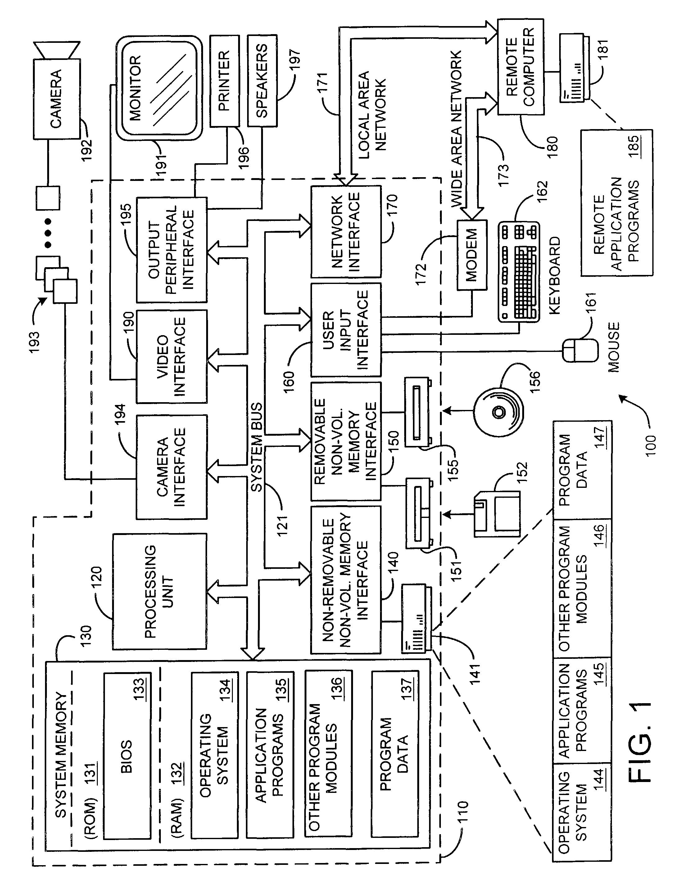
[0071]One working embodiment employing the camera 502 and microphone array 504 of the invention is shown in FIG. 5. The image output of the camera 502 and the audio output of the microphone array 504 is routed via an analog to digital converter 506 to a computer 508. The computer 508 performs various functions to enhance and utilize the image and audio input. For instance, a panoramic filter module 510 stitches together images that are taken by various sensors in the omni-directional camera 502. Additionally, the image data can be compressed by a compression module 512 to make it more compatible for broadcast 514 over a network (such as the Internet) or saved to a computer readable medium 516 (preferably via a splitter 520). Optionally, the image data can also be input into a person detector / tracker module 522 to improve camera management 524. For instance, the portions of the image / video containing the speaker can be identified, and associated with t...


PUM


Abstract

An omni-directional camera (a 360 degree camera) is proposed with an integrated microphone array. The primary application for such a camera is videoconferencing and meeting recording, and the device is designed to be placed on a meeting room table. The microphone array is in a planar configuration, and the microphones are located as close to the desktop as possible to eliminate sound reflections from the table. The camera is connected to the microphone array base with a thin cylindrical rod, which is acoustically invisible to the microphone array for the frequency range [50-4000] Hz. This provides a direct path from the person talking to all of the microphones in the array, and can therefore be used for sound source localization (determining the location of the talker) and beam-forming (improving the sound quality of the talker by filtering only sound from a particular direction). The camera array is elevated from the table to provide a near frontal viewpoint of the meeting participants.

Description

BACKGROUND[0001]1. Technical Field[0002]This invention is directed toward an integrated omni-directional camera and microphone array. More specifically, this invention is directed towards an integrated omni-directional camera and microphone array that can be used for teleconferencing and meeting recording.[0003]2. Background Art[0004]Video conferencing systems have had limited commercial success. This is due to many factors. In particular, there are typically numerous technical deficiencies in these systems. Poor camera viewpoints and insufficient image resolution make it difficult for meeting participants to see the person speaking. This is compounded by inaccurate speaker detection (especially for systems with pan-tilt-zoom cameras) that causes the camera not to be directed at the person speaking. Additionally, poor video compression techniques often result in poor video image quality and “choppy” image display.[0005]The capturing devices of systems used for teleconferencing tend ...

Claims


Application Information

Patent Timeline
Patent Type & Authority Patents(United States)
IPC IPC(8): H04N7/14H04N5/225H04N5/232H04N7/15H04R1/00H04R3/00
CPCH04N5/2259H04N5/23203H04R3/02H04N7/142H04R2201/401H04N23/58H04N23/66H04N7/15
Inventor CUTLER, ROSSTASHEV, IVANRUI, YONGGUPTA, ANOOP
Owner MICROSOFT TECH LICENSING LLC
Why Eureka
Try Eureka