Systems and methods for measurement and analysis of pipeline contaminants

a technology of pipeline contaminants and systems, applied in the direction of sampling, instruments, measurement devices, etc., can solve the problems of foul heat exchangers, wear rotating components, and extremely sensitive contamination of turbines and other critical gas or fluid flow systems used in the energy industry, so as to minimize the presence of aerosol contaminants, and minimize the effect of aerosol contaminants

Inactive Publication Date: 2010-12-21
PECOFACET US
View PDF19 Cites 5 Cited by
  • Summary
  • Abstract
  • Description
  • Claims
  • Application Information

AI Technical Summary

Benefits of technology

[0008]The present invention provides, in one embodiment, a system for measurement and analysis of pipeline contaminants. The system includes a first assembly for engaging a pipeline and from which a first fluid flow sample may be obtained for measurement of aerosol contaminants. In an embodiment, the first assembly may be provided with a first assembly probe for extending into the pipeline for isokinetically collecting the fluid flow sample to ensure that a representative amount of contaminants within the pipeline can subsequently be measured. The first assembly may also be provided with a particle counter, in fluid communication with the probe, for measuring a number and size of aerosol particles within the fluid flow sample. The resulting information can subsequently be used to obtained a mass content of the aerosol particles, so as to permit a selection of an appropriate extraction technology to control the presence of aerosol contaminants within the pipeline. The system further includes a second assembly for engaging the pipeline and from which a second fluid flow sample may be obtained for chromatographic analysis of the aerosol contaminants. In an embodiment, a location on the pipeline to which the first assembly and the second assembly engage may be a same location. Alternatively, a location on the pipeline to which the first assembly and second assembly engage may be spatially situated from one another. The second assembly, in an embodiment, may be provided with a second assembly probe for extending into the pipeline for isokinetically collecting the fluid flow sample to ensure that a representative amount of aerosol contaminants within the pipeline can subsequently be analyzed. The second assembly may also be provided with a cylinder coupled to the second assembly probe for housing the fluid flow sample directed from the second assembly probe. A chromatograph may further be provided in fluid communication with the cylinder for determining constituents of the fluid flow sample in order to identify the origin of the aerosol contaminants. In that way, corrective measures can be implemented to minimize the presence of aerosol contaminants.
[0009]The present invention further provides a method for measurement and analysis of pipeline contaminants. In an embodiment, the method includes initially extending a first probe into a fluid flow within a pipeline, so that aerosol contaminants can subsequently be measured. Then, a first fluid flow sample may be isokinetically collected in the first probe. Next, the collected first fluid flow sample may be directed from the first probe into a particle counter. Thereafter a number and size of aerosol particles within the fluid flow sample may be measured within a particle counter. The resulting information can subsequently be used to obtained a mass content of the aerosol particles. Knowledge of the mass content can permit a selection of an appropriate extraction technology to control the presence of aerosol contaminants within the pipeline. The method further includes extending a second probe into the fluid flow within a pipeline, so that constituents of the fluid flow sample can subsequently be determined in order to identify the origin of the aerosol contaminants. In one embodiment, extending the second probe within the pipeline includes removing the first probe prior to extending the second probe into a same area of the pipeline. Alternatively, the first probe and second probe may be placed at locations spatially situated from one another. Next, the second fluid flow sample may be isokinetically collected in the second probe. In an embodiment, the isokinetically collected first fluid flow sample and second fluid flow sample may be collected substantially simultaneously with one another. Thereafter, the collected second fluid flow sample may be directed from the second probe into a chromatograph. In one embodiment, prior to directing the second fluid flow sample into the chromatograph, the second fluid flow sample may be stored in a cylinder. Constituents of the fluid flow sample may then be determined in order to identify the origin of the aerosol contaminants, so that corrective measures can be implemented to minimize the presence of aerosol contaminants.
[0010]The present invention further provides another method for measurement and analysis of pipeline contaminants. The method includes initially extending a first probe and a second probe into a fluid flow within a pipeline at locations spatially situated from one another, so that contaminants can subsequently be determined. Then, a first fluid flow sample and a second flow sample may be isokinetically collected substantially simultaneously in their respective probes. Next, the collected first fluid flow sample may be directed from the first probe into a particle counter, while the collected second fluid flow sample may be directed from the second probe into a chromatograph. In an embodiment, the collected second fluid flow sample may be stored in a cylinder prior to being directed to the chromatograph. Subsequently, a number and size of aerosol contaminants within the first fluid flow sample may be measured within the particle counter. This information can subsequently be used to obtained a mass content of the aerosol contaminants, so as to permit a selection of an appropriate extraction technology to control the presence of aerosol contaminants within the pipeline. Additionally, constituents of the second fluid flow sample may be determined in order to identify the origin of the aerosol contaminants, so that corrective measures can be implemented to minimize the presence of aerosol contaminants.

Problems solved by technology

Current commercially available gas turbines and other critical gas or fluid flow systems for use in connection with the energy industry can be extremely sensitive to contamination, such as, solid contaminants (i.e., particulates), liquid contaminants, and / or liquid aerosol, present within the process fluid flow.
Solid contaminants, as an example, can act to wear rotating components, foul heat exchangers, contaminate cooling liquids, clog processing equipment, as well as affecting numerous other processing and equipment problems.
Liquid contaminants, on the other hand, can accumulate or coalesce over time, and can, as the volume increases, travel along the sides and bottom of a pipeline and affect the efficiency of the fluid flow.
Likewise, liquid aerosol or droplets, although small in mass, can similarly accumulate and build up over time, and have damaging effects on downstream equipment in the fluid flow system.
However, the issue with liquid contaminants or liquid aerosols may remain.
Moreover, the selection of filtration and separation equipment that can provide adequate removal of the right contaminants can be a difficult task.
As a result, unless there is knowledge about the contaminants within the fluid flow, as well as their characteristics, inadequate filtration and separation equipment may be selected, purchased and subsequently installed.
The failure to employ optimal or at least appropriate filtration and separation equipment, in many instances, can lead to inadequate removal of the contaminants resulting in damage to downstream equipment.
In addition, operational costs of the system can be significantly higher as a result of poor performance caused by insufficient removal of the contaminants.
However, in many instances, a substantially accurate sample may not be available, especially when the sample cannot be isokinetically collected.
In other words, if fluid entering the sampling system does not exhibit similar velocity and kinetic energy to the fluid flow in the pressurized process fluid flow, an accurate representation of contaminants within the fluid flow may not be collected.
During this period, the sample can change and the contaminants can often be lost to the sample container.
Furthermore, as a number of contaminants may be volatile in nature, and due to the time consuming approach of the present protocol, many of the contaminant samples never get sent off for analysis.
Nevertheless, regardless of how sensitive or accurate the analyzers or counter may be, since the collected samples may not be an adequate representation of the contaminants within the fluid flow, the subsequent analysis of the collected samples may not provide an accurate picture or a real time determination of the level of contaminants within the fluid flow.
Moreover, knowledge of the amount or level of contaminants does not necessarily help to identify the source of the contaminants.

Method used


Image

  • Systems and methods for measurement and analysis of pipeline contaminants
  • Systems and methods for measurement and analysis of pipeline contaminants
  • Systems and methods for measurement and analysis of pipeline contaminants

Examples


Embodiment Construction

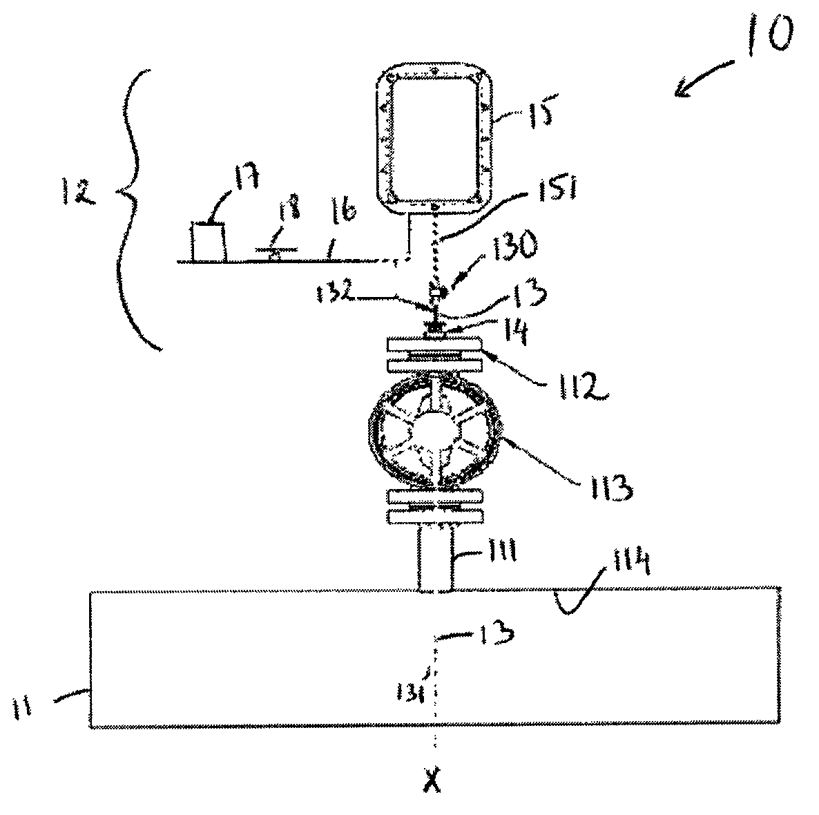
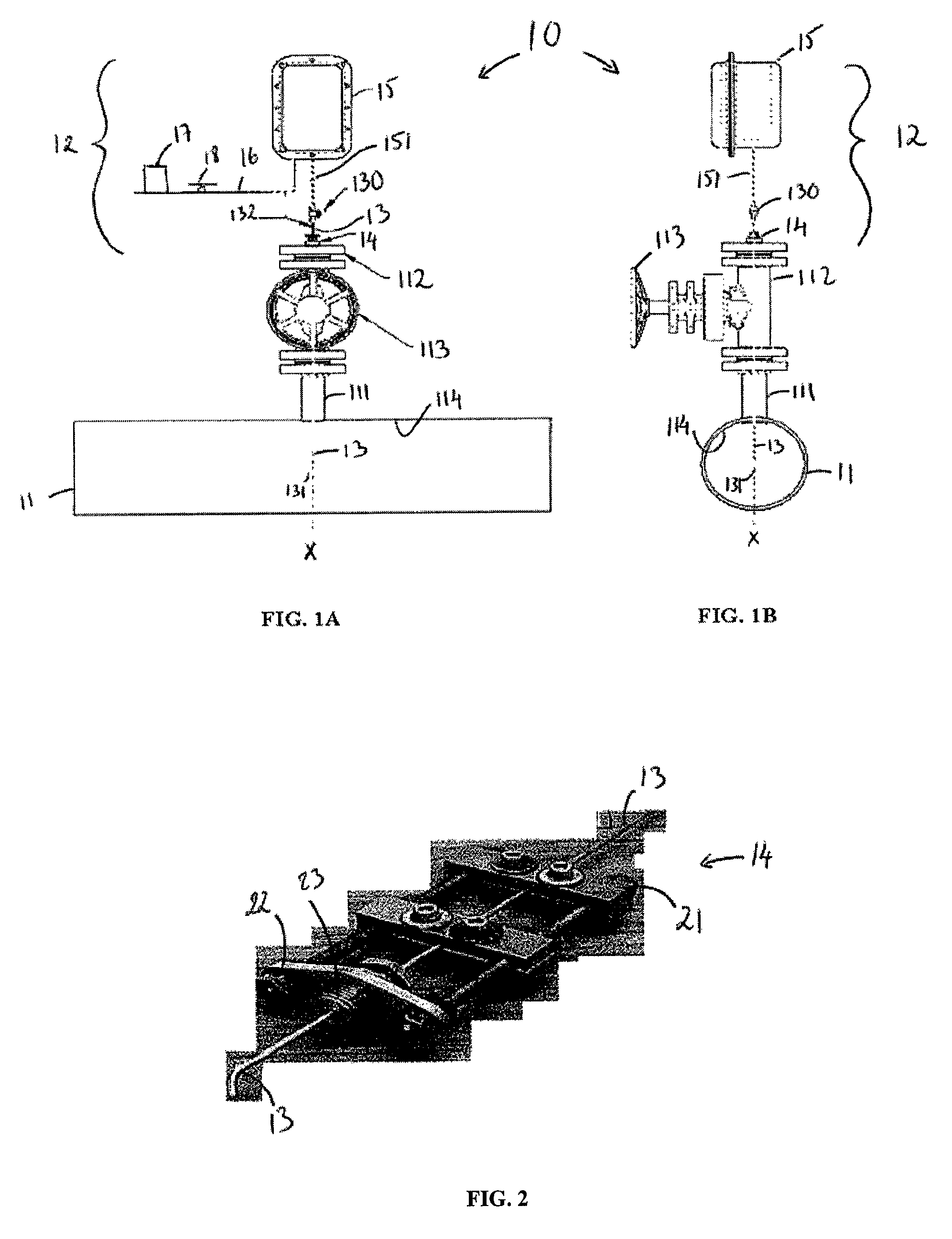
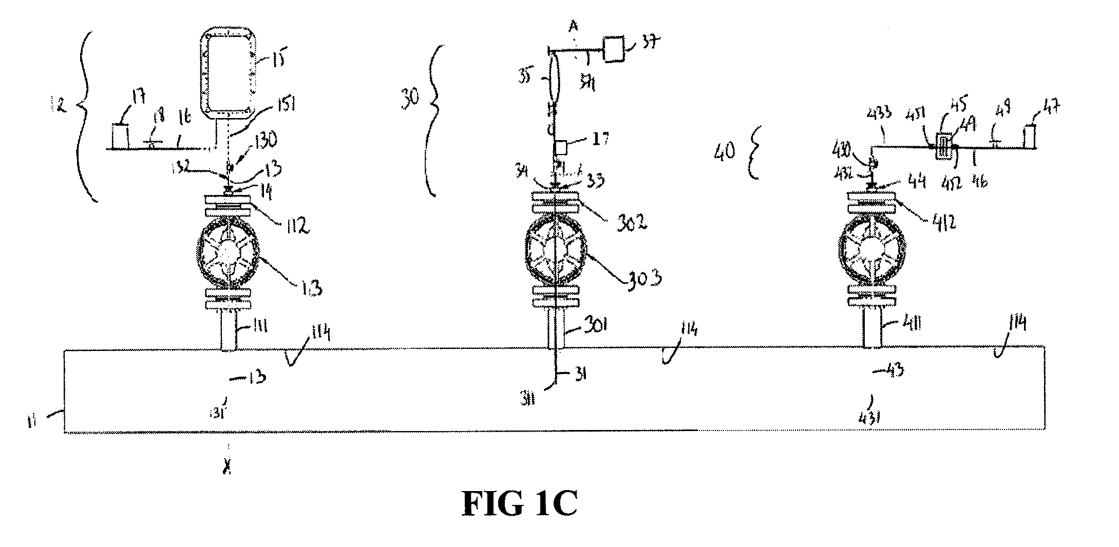
[0017]With reference to FIGS. 1A-B, the present invention provides, in one embodiment, a system 10 for use in the measurement and analysis of contaminants within a fluid flow system, such as pipeline 11. System 10, in an embodiment, may include a contaminant measurement assembly 12 designed to engage pipeline 11 by way of a sampling nozzle 111. Nozzle 111, as illustrated, may be situated at any desired point along pipeline 11 and provides an opening through which assembly 12 may communicate with the fluid flow within pipeline 11. To prevent fluid flow from escaping through the sampling nozzle 111 when assembly 12 may not be in engagement therewith or when assembly 12 is not in use, sampling nozzle 111 may include a valve, such as isolation valve 112, which can be actuated between an open and closed position, for example, by way of wheel 113.

[0018]In accordance with one embodiment, assembly 12 includes a probe 13 designed for transporting a fluid sample from within the pipeline 11 to...


PUM

PropertyMeasurementUnit
velocityaaaaaaaaaa
velocityaaaaaaaaaa
angleaaaaaaaaaa

Abstract

A system for measurement and analysis of pipeline contaminants is provided. The system includes a first assembly for engaging a pipeline from which a first fluid flow sample may be isokinetically collected for measurement of aerosol contaminants. The system also includes a second assembly for engaging the pipeline from which a second fluid flow sample may be collected for chromatographic analysis of the aerosol contaminants. The system may further include a third assembly for engaging the pipeline from which a fluid flow sample may be obtained for measurement of solid contaminants. Information on aerosol contaminants and solid contaminants can subsequently be used to select an appropriate extraction technology to control the presence of aerosol and solid contaminants within the pipeline. Information from the chromatographic analysis, on the other hand, may be used to identify the origin of the aerosol contaminants, so that corrective measures can be implemented to minimize the presence of aerosol contaminants within the pipeline. A method for measurement and analysis of pipeline contaminants is also provided.

Description

TECHNICAL FIELD[0001]The present invention relates to systems and methods for measurement of contaminants, and more particularly, to the isokinetic sampling, measurement, and analysis of contaminants in a fluid flow within a pipeline to aid in the control of these contaminants.BACKGROUND ART[0002]Current commercially available gas turbines and other critical gas or fluid flow systems for use in connection with the energy industry can be extremely sensitive to contamination, such as, solid contaminants (i.e., particulates), liquid contaminants, and / or liquid aerosol, present within the process fluid flow. Solid contaminants, as an example, can act to wear rotating components, foul heat exchangers, contaminate cooling liquids, clog processing equipment, as well as affecting numerous other processing and equipment problems. Liquid contaminants, on the other hand, can accumulate or coalesce over time, and can, as the volume increases, travel along the sides and bottom of a pipeline and ...

Claims


Application Information

Patent Timeline
Patent Type & Authority Patents(United States)
IPC IPC(8): G01N30/02G01N30/90
CPCG01N15/0205G01N2001/2223G01N2015/1486G01N2030/8886G01N2001/225
Inventor BURNS, DAVIDBORJON, TOMASSCOTT, MARK
Owner PECOFACET US
Why Eureka
Try Eureka