Pontoonless tension leg platform

a technology of tension leg and platform, which is applied in the direction of special-purpose vessels, vessel construction, transportation and packaging, etc., to achieve the effect of increasing the buoyancy of columns and increasing the diameter (and/or cross-sectional area)

Inactive Publication Date: 2010-12-21
SEAHORSE EQUIP
View PDF44 Cites 17 Cited by
  • Summary
  • Abstract
  • Description
  • Claims
  • Application Information

AI Technical Summary

Benefits of technology

[0030]A TLP according to the present invention eliminates the subsea pontoons which extend between the surface-piercing columns of the TLPs of the prior art. Structural elements above the water surface provide the rigidity typically furnished by the pontoons of multi-column TLPs of the prior art. In certain embodiments, the buoyancy of the columns is increased by the addition of subsea sections of increased diameter (and / or cross-sectional area) to provide the buoyancy furnished by the pontoons of the TLPs of the prior art.
[0031]Certain embodiments of the invention feature a deck support structure comprising plate-type trusses or “box beams” which may assume a variety of configurations. Other embodiments of the invention have a deck support structure comprising open-type trusses. Gussets or similar above-water braces between the deck support structure and the surface-piercing columns act to further increase the rigidity and structural strength of the platform.
[0032]A pontoonless TLP according the invention has a smaller subsea projected area in both the horizontal and vertical planes than a conventional multi-column TLP of equivalent load-bearing capacity having pontoons between the columns. This reduction in surface area results in a reduction in the platform's response to ocean currents and wave action which consequently allows the use of smaller and more economical mooring systems. Additionally, the smaller vertical projected area results in a shorter natural period which enables a TLP according to the present invention to be deployed in greater water depths where conventional TLPs cannot be used due to their longer natural periods.
[0033]The elimination of pontoons from a multi-column TLP has the added benefit of providing an unobstructed path for risers to connect with the deck of the platform. In TLPs of conventional design, risers must typically be supported on subsea pontoons because supporting the riser from the deck would risk mechanical contact between the riser and pontoon below it. Installation and maintenance of the riser support and fluid connection to the riser are both facilitated by locating it on the deck rather than having it below the surface of the water.

Problems solved by technology

In TLPs of conventional design, risers must typically be supported on subsea pontoons because supporting the riser from the deck would risk mechanical contact between the riser and pontoon below it.

Method used


Image

  • Pontoonless tension leg platform
  • Pontoonless tension leg platform
  • Pontoonless tension leg platform

Examples


first embodiment

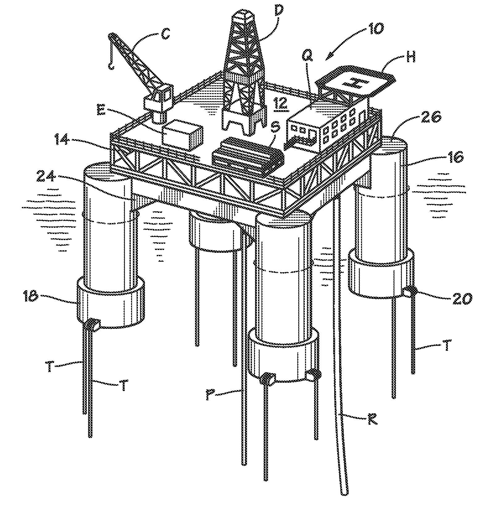
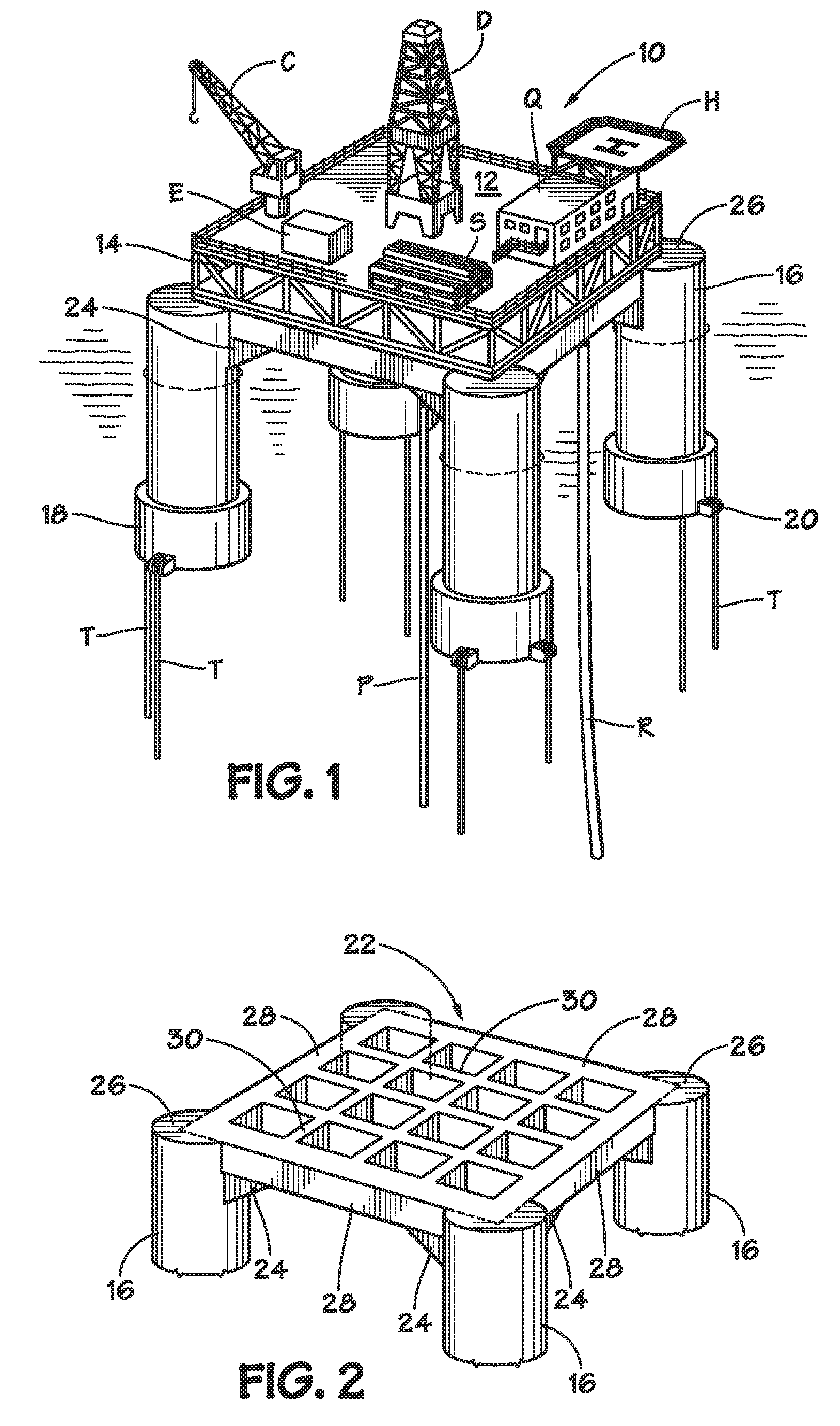
[0038]The invention may best be understood by reference to certain illustrative embodiments. FIG. 1 depicts a TLP 10 according to the invention installed at an offshore location. As is conventional for tension leg platforms, the buoyant hull of the vessel (comprised of columns 16) is anchored to the seafloor by tendons T which are tensioned to hold the vessel such that the waterline in its installed condition is above that of its free-floating state. This arrangement eliminates most vertical movement of the structure.

[0039]TLP 10 comprises a deck 12 which may be configured to suit the particular needs of the owner or operator. A typical deck layout for a drilling operation is shown in FIG. 1 and includes derrick D, helicopter landing facility H, crew quarters Q, loading crane C, equipment E and supplies S. Catenary risers R and vertical risers P may be supported by the TLP from deck 12.

[0040]Framework 14 allows deck 12 to be a separate, detachable unit thereby facilitating both fabr...

third embodiment

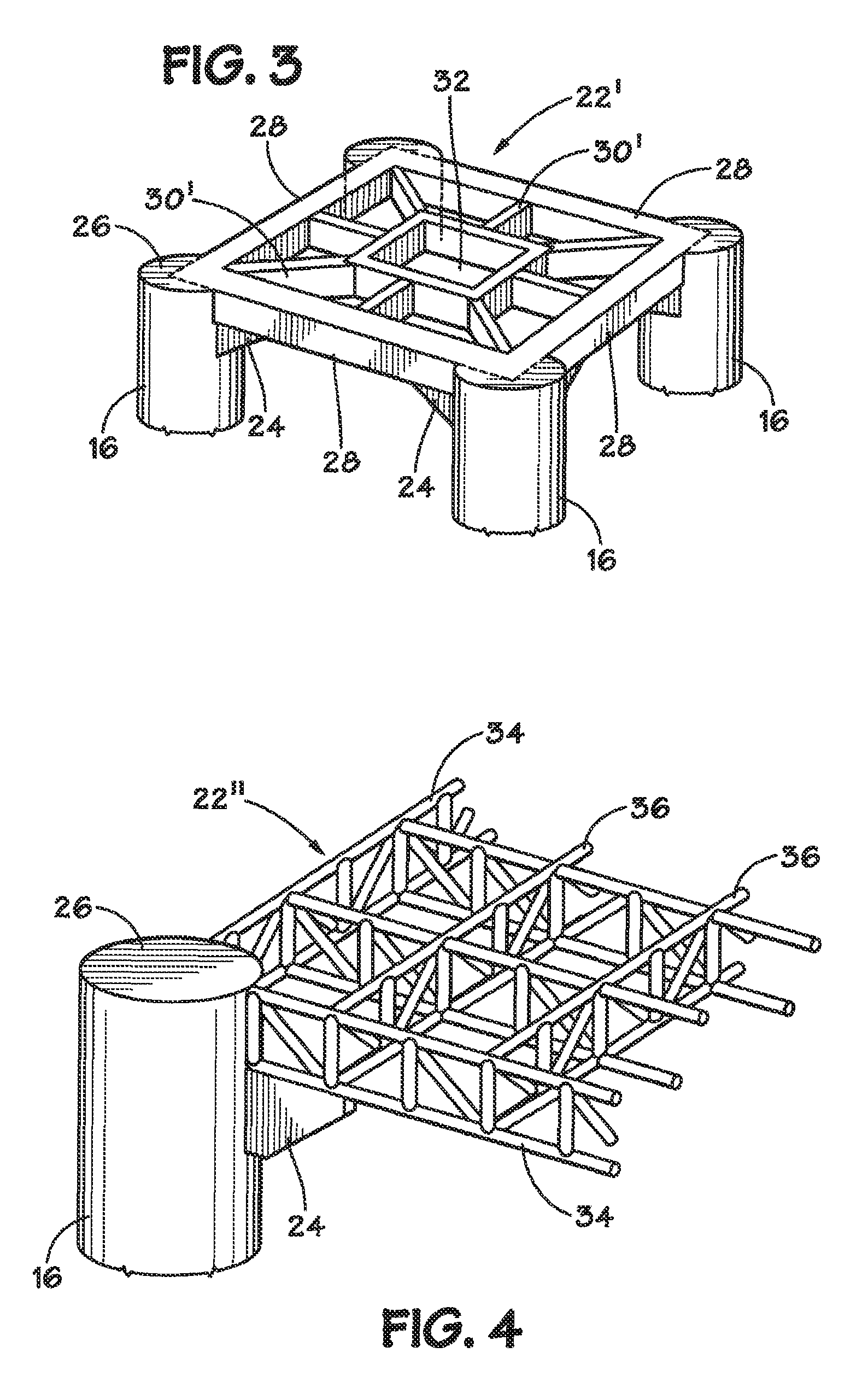
[0048]FIG. 4 illustrates the invention wherein deck support structure 22″ is comprised of an open truss framework. Perimeter members 34 connect adjacent columns 16 and may support the perimeter of deck 12. Generally orthogonal interior trusses 36 connect opposing perimeter members 34 and provide interior support for deck 12. The trusses may be constructed from flanged members including Z-Shape (half a flange in opposite directions), HSS-Shape (hollow structural section also known as SHS (structural hollow section) and including square, rectangular, circular (pipe) and elliptical cross-sections), angle (L-shaped cross-section), channel (C-shaped cross-section), tee (T-shaped cross-section), or any other configuration having the requisite structural properties.

[0049]In the embodiment illustrated in FIG. 4, deck support structure 22″ is comprised of parallel chord or “flat” trusses. Many flat truss designs are known in the art. Examples include the Pratt configuration, the Warren confi...


PUM


Abstract

A pontoonless tension leg platform (TLP) has a plurality of buoyant columns connected by an above-water deck support structure. The design eliminates the need for subsea pontoons extending between the surface-piercing columns. In certain embodiments, the buoyancy of the columns is increased by the addition of subsea sections of increased diameter (and / or cross-sectional area) to provide the buoyancy furnished by the pontoons of the TLPs of the prior art. A pontoonless TLP has a smaller subsea projected area in both the horizontal and vertical planes than a conventional multi-column TLP of equivalent load-bearing capacity having pontoons between the columns. This reduction in surface area produces a corresponding reduction in the platform's response to ocean currents and wave action and consequently allows the use of smaller and / or less costly mooring systems. Moreover, the smaller vertical projected area results in a shorter natural period which enables a pontoonless TLP according to the invention to be used in water depths where conventional TLPs cannot be used due to their longer natural periods. The absence of pontoons in a multi-column TLP also has the added benefit of providing an unobstructed path for risers to connect with the deck of the platform.

Description

CROSS-REFERENCE TO RELATED APPLICATIONS[0001]NoneSTATEMENT REGARDING FEDERALLY SPONSORED RESEARCH OR DEVELOPMENT[0002]Not ApplicableBACKGROUND OF THE INVENTION[0003]1. Field of the Invention[0004]This invention relates to offshore platforms. More particularly, it relates to tension leg platforms (TLPs).[0005]2. Description of the Related Art Including Information Disclosed Under 37 CFR 1.97 and 1.98.[0006]A tension leg platform (TLP) is a vertically moored floating structure typically used for the offshore production of oil and / or gas, and is particularly suited for water depths greater than about 1000 ft.[0007]The platform is permanently moored by tethers or tendons grouped at each of the structure's corners. A group of tethers is called a tension leg. The tethers have relatively high axial stiffness (low elasticity) such that virtually all vertical motion of the platform is eliminated. This allows the platform to have the production wellheads on deck (connected directly to the sub...

Claims


Application Information

Patent Timeline
Patent Type & Authority Patents(United States)
IPC IPC(8): B63B35/44
CPCB63B35/44B63B21/502B63B1/107
Inventor HEIDARI, AMIR HOMAYOUN
Owner SEAHORSE EQUIP
Why Eureka
Try Eureka