Code generation apparatus
a code generation and code technology, applied in multiplex communication, instruments, reradiation, etc., can solve the problems of difficult to change the pn code upon request, difficult to change the tap location, etc., and achieve the effect of dramatically improving the degree of freedom in correlation operation and high interference resistan
- Summary
- Abstract
- Description
- Claims
- Application Information
AI Technical Summary
Benefits of technology
Problems solved by technology
Method used
Image
Examples
first embodiment
[0100]Hereinafter, a first embodiment of the present invention shall be described with reference to the drawings.
[0101]The code generation apparatus in the present embodiment includes characteristics shown in (a) to (d) below.
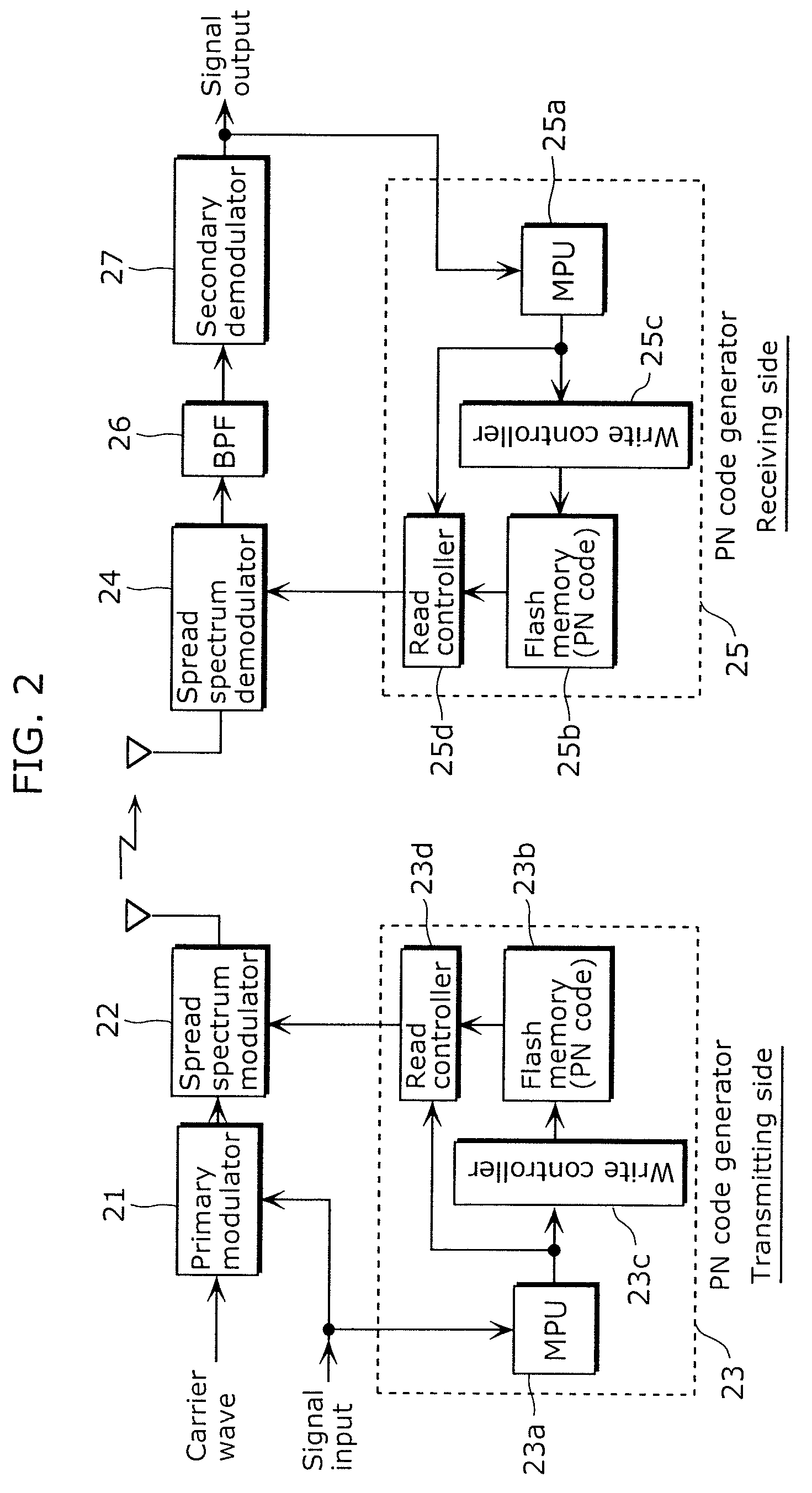
[0102](a) The code generation apparatus includes the following functions: (a1) a clock signal generation function to generate a clock signal of a first frequency; (a2) a timing signal generation function to generate, according to the clock signal, a timing signal of a second frequency lower than the first frequency; (a3) a storage function to store a plurality of code sequences serving as a source for a pseudo-noise code; (a4) a code sequence selection function to select, according to the timing signal, a code sequence to be read, from among the plurality of code sequences stored by the storage function; (a5) a partial code sequence extraction function to extract, as a partial code sequence, a code of a predetermined bit length, from the code sequence selected ...
second embodiment
[0173]Hereinafter, a second embodiment of the present invention shall be described with reference to the drawings.
[0174]A code generation apparatus according to the present embodiment includes characteristics shown in (e) below.
[0175](e) A partial code sequence extraction function includes: (e1) a first partial code sequence extraction function to read a first code sequence part from a code sequence selected by a code sequence selection function, and to extract a code of a predetermined bit length from the first code sequence part; (e2) a second partial code sequence extraction function to read a second code sequence part from the code sequence selected by the code sequence selection function, and to extract a code of a predetermined bit length from the second code sequence part; (e3) a partial code sequence selection function to alternately select the first partial code sequence extraction function and the second partial code sequence extraction function, and to output, as a partia...
third embodiment
[0185]Hereinafter, a third embodiment of the present invention shall be described with reference to the drawings.
[0186]The code generation apparatus according to the present embodiment includes characteristics shown in (f) below.
[0187](f) The code generation apparatus includes: (f1) a code generation function to generate a pseudo-noise code; (f2) a code holding function to hold a 2X−1 bit code from the code generated by the code generating function; (f3) a write control function to cause: initially, the 2X−1 bit code from the code held by the code holding function to be stored in a predetermined storage destination in the storage function, when the 2X−1 bit code is held by the code holding function; and, subsequently, a 2X−1 bit code newly held by the code holding function to be stored in a new storage destination in the storage function, when a new X-bit code is held by the code holding function.
[0188]Based on the above point, the code generation apparatus in the present embodiment...
PUM
 Abstract
Description
Claims
Application Information
 - R&D
- Intellectual Property
- Life Sciences
- Materials
- Tech Scout
- Unparalleled Data Quality
- Higher Quality Content
- 60% Fewer Hallucinations
Browse by: Latest US Patents, China's latest patents, Technical Efficacy Thesaurus, Application Domain, Technology Topic, Popular Technical Reports.
© 2025 PatSnap. All rights reserved.Legal|Privacy policy|Modern Slavery Act Transparency Statement|Sitemap|About US| Contact US: help@patsnap.com


