Modular heat sinks for housings for electronic equipment

a technology of electronic equipment and heat sinks, which is applied in the direction of electrical apparatus construction details, semiconductor/solid-state device details, lighting and heating apparatus, etc., can solve the problem of very expensive design and fabrication of new castings

Active Publication Date: 2010-12-21
ADTRAN
View PDF19 Cites 32 Cited by
  • Summary
  • Abstract
  • Description
  • Claims
  • Application Information

AI Technical Summary

Problems solved by technology

The design and fabrication of a new casting is very expensive.

Method used


Image

  • Modular heat sinks for housings for electronic equipment
  • Modular heat sinks for housings for electronic equipment
  • Modular heat sinks for housings for electronic equipment

Examples


Embodiment Construction

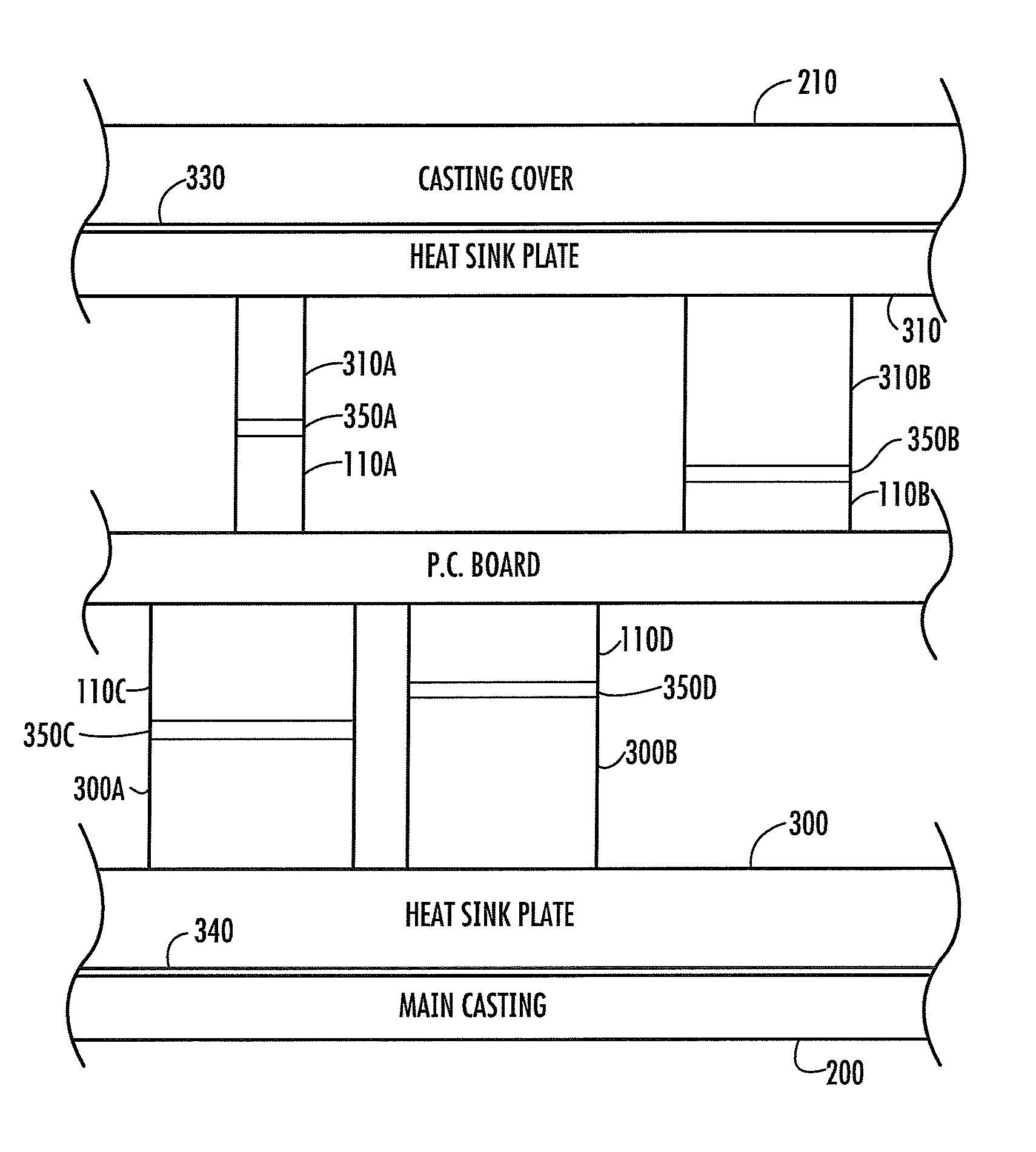
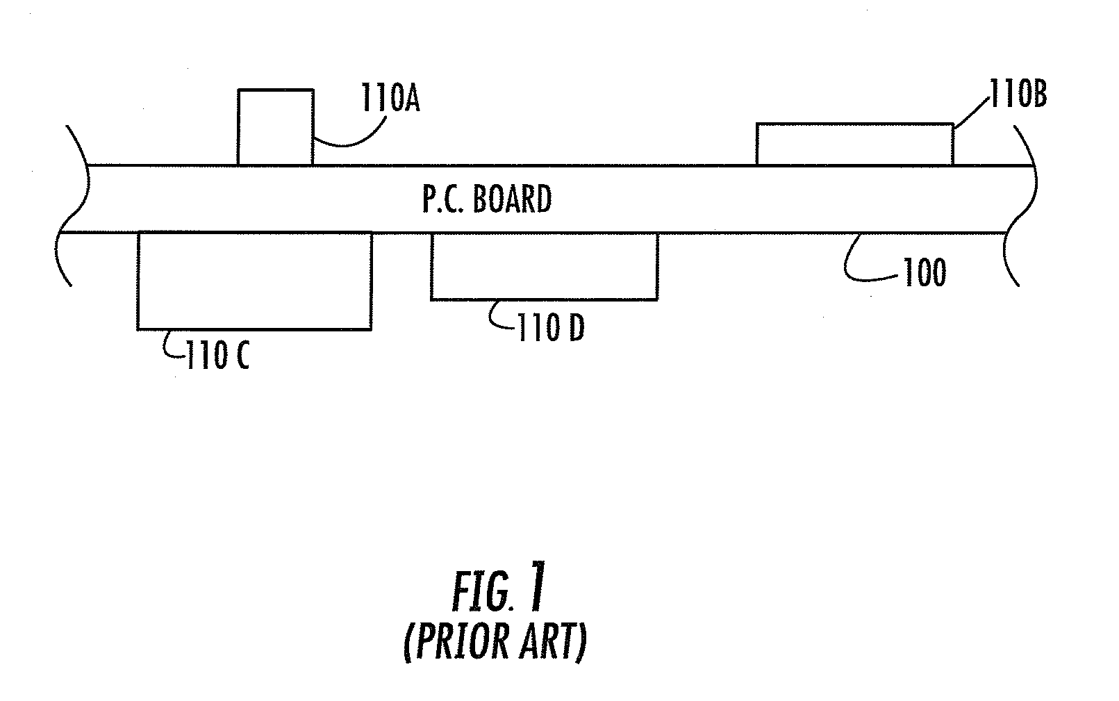
[0017]FIG. 1 is a simplified side view of an exemplary double-sided printed circuit board as known in the prior art. The printed circuit board consists of a substrate 100 which includes electrically conducting paths connecting electronic components mounted on the surface of the printed circuit board. Such components are shown in FIG. 1 as items 110A, 110B, 110C and 110D. The number and arrangement of electronic components on the printed circuit board vary from design to design. Some printed circuit boards are single-sided. That is, their electronic components mount principally on one side of the board. Some printed circuit boards also contain multiple layers of conducting paths embedded at different depths within the printed circuit board substrate.

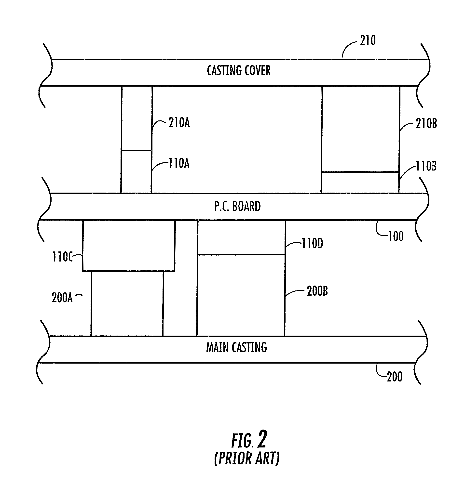
[0018]Some of the electronic components mounted on printed circuit boards dissipate a substantial amount of heat. The problem of dissipating heat from the electronic components is particularly noticeable when the electronic components are...


PUM


Abstract

A housing for an outside plant telecommunication equipment (OSP) which uses modular heat sink assemblies. OSP housings contain electronic circuit boards on which are mounted electrical components that generate heat. Thermal conductors or mesas contact the electrical components to conduct heat from the components to the environment. Rather than create single purpose housings with cast thermal conductors, the improved housing uses heat sink plates which can easily be swapped out to accommodate a variety of electronic circuit boards that might be needed within a general purpose housing. Together with faster turnaround time to create a new design for a housing, lower manufacturing and inventory costs result.

Description

BACKGROUND OF THE INVENTION[0001]1. Field of the Invention[0002]The invention is related to heat sinks and more particularly to modular heat sinks for housings for electronic equipment.[0003]2. Description of the Prior Art[0004]Conventional housings for outside plant (OSP) telecommunication equipment, such as an ADTRAN TA1148 OSP housing, are typically designed for a specific product and generally are product limited. When a service provider, such as a telecommunications company, requires significant changes to an OSP product or a manufacturer introduces a new product, it is often necessary to provide a new OSP housing. When the new housing requires geometric (i.e., size, material thickness, etc.) and other changes, such changes usually add cost and undesirable manufacturing delay. Hence a new housing, though required, has undesirable consequences. As such, there is a need for an improved housing that is readily available to meet new specifications and that reduces cost and delays. ...

Claims


Application Information

Patent Timeline
Patent Type & Authority Patents(United States)
IPC IPC(8): H05K7/20F28F7/00H01L23/34
CPCH05K7/20445H05K7/20454H01L23/4093H01L23/42H01L23/433H01L2924/0002H01L2924/00
Inventor AYRES, III, JOHN WISEKRUSE, GRANT JOSEPHMCCLEARY, JACOB DANIEL
Owner ADTRAN
Why Eureka
Try Eureka