Body-side suspension strut bearing for wheel suspensions

a technology of suspension strut and bearing, which is applied in the direction of shock absorbers, couplings, transportation and packaging, etc., can solve the problems of the spring plate which borders the ball and socket joint on the piston rod of the shock absorber, the risk of the ball head “popping” out of the socket, and the magnitude of the force to be transmitted is very limited, so as to facilitate the tensile load and facilitate the installation of universal joints.

Inactive Publication Date: 2010-12-28
AUDI AG
View PDF12 Cites 7 Cited by
  • Summary
  • Abstract
  • Description
  • Claims
  • Application Information

AI Technical Summary

Benefits of technology

[0006]It is proposed according to the invention that the joint be formed by a universal joint with two crossing axes of rotation. The universal joint can be loaded the same in the directions of compression and tension and is thus especially durable. Furthermore, it is simple in terms of production engineering and requires little installation space, especially in the axial direction of the suspension strut.
[0007]In one advantageous development the universal joint can be connected between the body of the vehicle and the absorber bearing. This results in that the coupling and support of the upper spring plate, the piston rod of the shock absorber and optionally a stop buffer as an additional spring can remain structurally unchanged, and no disadvantageous compromises need be made.
[0009]For this purpose the pivot bearings of the receiving ring and of the housing ring can lie in a uniform joint plane, by which the overall height of the universal joint can be further reduced.
[0012]In contrast to the ball and socket joint solution known from the prior art, in the universal joint according to the invention the pivot pins project rotationally symmetrically enclosed into the receiving ring, the joint retainer and / or the housing ring. In this way the universal joint, in contrast to the ball and socket joint solution, can also easily withstand tensile loads without the risk of parts of the universal joint “popping out”.
[0013]To achieve a simple installation capacity of the universal joint, the pivot pins of the pivot bearings between the spider and the housing ring can be screwed from the outside to the inside into the spider and the bearing bolts of the pivot bearings can be screwed from the outside to the inside into the receiving ring between the receiving plate and the spider. First the spider with the housing ring and then the receiving ring are mounted accordingly on the spider.
[0014]The above described suspension strut bearing can preferably be used on a suspension strut with integrated adjustment of the level of the vehicle body, the adjusting device being provided with a ball screw drive which is located around the telescoping shock absorber and which adjusts the spring plate of the bearing spring relative to the body by an electric motor by way of a pivot-mounted threaded spindle and a nut screw which is supported to be able to move axially. In the preferred use, the transverse forces and squeezing both on the piston rod of the shock absorber and also on the adjustment device can be eliminated with the ball screw drive.

Problems solved by technology

Moreover, the coupling and support of the spring plate which borders the ball and socket joint on the piston rod of the shock absorber can be a problem.
When the ball and socket joint is loaded in tension, however, there is the risk of the ball head “popping” out of the socket.
Under tensile loading the magnitude of the force to be transmitted is very limited.
Another disadvantage is that the ball pivot is not located at the center of mass of the surface of the rubber-metal bearing.
This solution is advantageous in terms of vibration engineering, but the above described transverse forces and squeezing on the suspension strut cannot be precluded.

Method used


Image

  • Body-side suspension strut bearing for wheel suspensions
  • Body-side suspension strut bearing for wheel suspensions
  • Body-side suspension strut bearing for wheel suspensions

Examples


Embodiment Construction

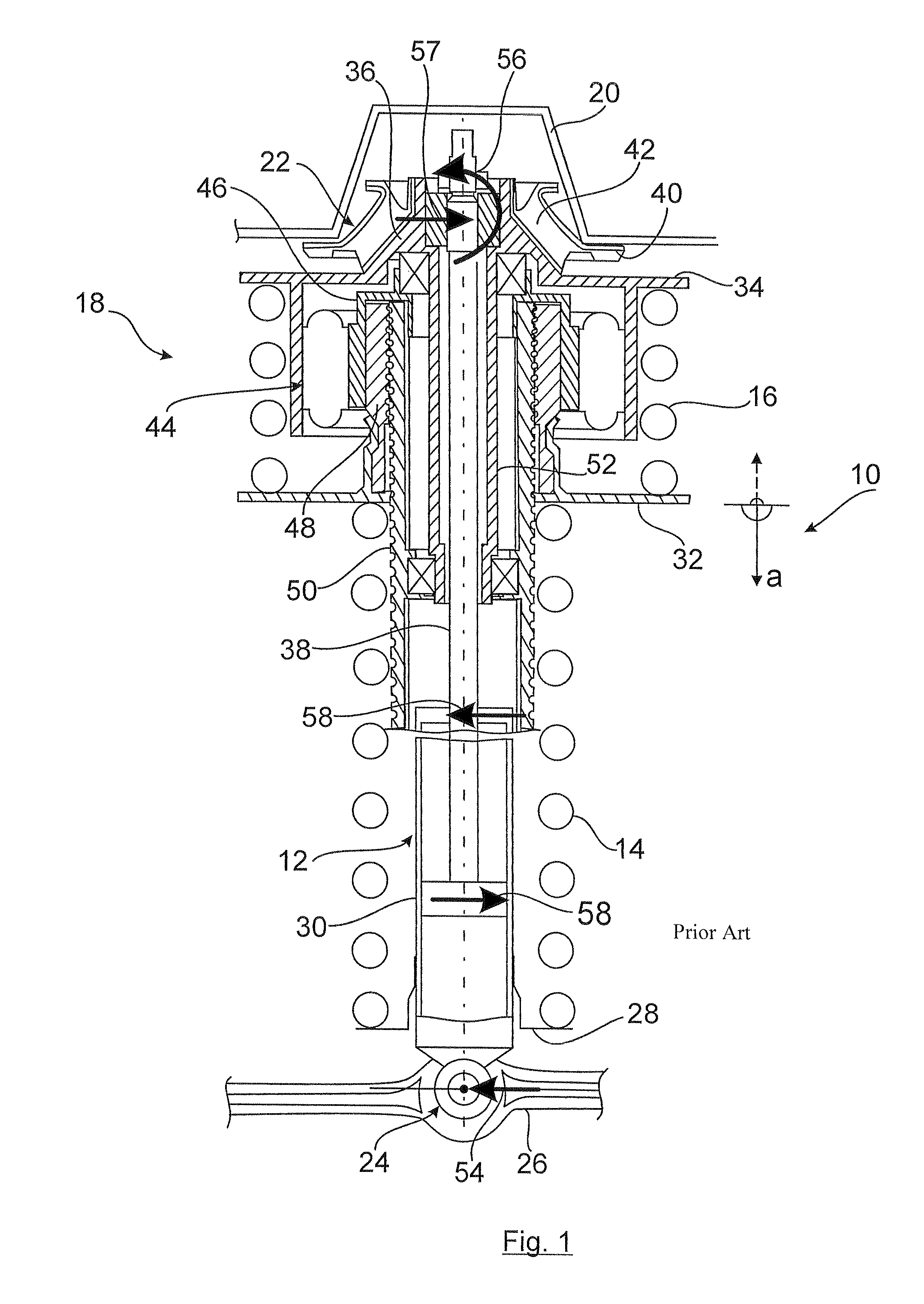
[0020]FIG. 1 shows a suspension strut 10 which corresponds to the prior art according to DE 10 2005 001 744 B3, with a telescoping shock absorber 12, a bearing spring 14 which is formed by a helical compression spring, a compensating spring 16 and a height adjustment device 18.

[0021]The suspension strut 10 as a part of the wheel suspension for a motor vehicle on the one hand is coupled to the body 20 by way of a shock absorber bearing 22 and on the other hand via a rubber-metal bush bearing 24 to a suspension arm 26 as the wheel suspension element of the wheel suspension.

[0022]The bearing spring 14 is firmly supported on its lower end via a spring plate 28 on the tube 30 of the shock absorber 12 and on its upper end adjoins the axially movable spring plate 32.

[0023]The compensating spring 16 which is likewise made as a helical compression spring is clamped between the spring plate 32 and the upper spring plate 34, the spring plate 34 being supported on the shock absorber bearing 22 ...


PUM


Abstract

The invention relates to a body-side suspension strut bearing for wheel suspensions of motor vehicles, with a suspension strut which consists at least of a telescoping shock absorber and a bearing spring, and which is supported by way of a shock absorber bearing on the body and by way of another bearing on the wheel suspension elements of the motor vehicle, there being a joint between the body and the suspension strut. A suspension strut bearing which is favorable in terms of construction, production engineering and function, is achieved by the joint being formed by a universal joint with two crossing axes of rotation.

Description

BACKGROUND OF THE INVENTION[0001]Such a suspension strut bearing is described in DE 10 2005 001 742 A1 in which the piston rod of the telescoping shock absorber of the suspension strut is connected via a ball and socket joint to the absorber bearing and the latter to the body of the vehicle. The ball and socket joint consists of a piston rod-side ball head which is supported in an absorber-side ball socket. The ball and socket joint makes it possible to avoid transverse forces which act on the piston rod of the shock absorber and which can occur as a result of pivoting motions of the wheel suspension elements, for example, of a suspension arm which is connected to the shock absorber.[0002]The illustrated ball and socket joint, however, must be designed to have a relatively large volume for reasons of design, in order to be able to withstand especially dynamic loads in the direction of compression and tension. Moreover, the coupling and support of the spring plate which borders the b...

Claims


Application Information

Patent Timeline
Patent Type & Authority Patents(United States)
IPC IPC(8): F16F9/54
CPCB60G17/021F16F9/54B60G2200/142B60G2202/312B60G2202/42B60G2204/124Y10T403/18B60G2204/128B60G2204/414B60G2500/30Y10T403/32041B60G2204/1242
Inventor WILFRIED, MICHEL
Owner AUDI AG
Why Eureka
Try Eureka