Cooling facility for cooling a component

a cooling facility and component technology, applied in the direction of insulated conductors, power cables, semiconductor/solid-state device details, etc., can solve the problems of increasing the space required for known arrangements, increasing the clock frequency of microprocessors, and increasing the power dissipation of microprocessors, so as to improve cooling performance and efficient cooling

Inactive Publication Date: 2010-12-28
SIEMENS AG
View PDF21 Cites 6 Cited by
  • Summary
  • Abstract
  • Description
  • Claims
  • Application Information

AI Technical Summary

Benefits of technology

[0006]For the heat sink mentioned at the outset, the object is inventively achieved in that, for cooling a component, a guidance of a main flow and of a secondary flow of the medium is present at least in some sections, with the main flow being separated from the secondary flow by a separation means up to a constriction point and the secondary flow and the main flow merging after the constriction. In accordance with the continuity law, in a flow channel which narrows for the main flow, a flow speed and thereby a dynamic pressure of the main flow will increase at the constriction point. A constriction point is taken to be the location which has the smallest cross section within the flow channel. Because of the increased volume flow produced by the constriction the ability of the main flow to accept heat increases and there is advantageously a greater cooling effect.
[0007]Advantageously the separation means is arranged with an underside in an angled position to a surface of the heat sink facing towards the component. It is of further advantage here for the separation means to be arranged within the heat sink. The heat sink within a module will thus take up less space, which leads to lower dimensions of the module.
[0010]In a further advantageous embodiment a cross section available for the main flow narrows down from a main flow entry to a constriction point. This type of continuously narrowing flow channel promotes the flow and the subsequent sucking in of the secondary flow after the constriction.
[0015]To boost the cooling power further a base plate is preferably arranged on the surface. This base plate allows transport of heat in the base plate from the component to be cooled in the direction of the main flow, with the base plate being in contact with the component.
[0017]Preferably the coolant flow generation means is arranged on the cooling fins such that it applies the medium over at least one opening between the cooling fins. This “pumping in” of for example pulsed air behind the constriction, viewed in the direction of flow, further improves the cooling performance.
[0018]For an electronic module with a housing and a heat sink an efficient cooling while adhering to a minimum required module size can be guaranteed.

Problems solved by technology

In addition shorter processing times of CPU modules in automation systems are demanded, which in its turn results in a higher clock frequency of microprocessors used and thus once again to a rise in the power dissipation of the microprocessor, especially with the CPU modules.
The disadvantage of the prior art is that the known arrangements demand an increased amount of space and can no longer take account of future cooling tasks.

Method used


Image

  • Cooling facility for cooling a component
  • Cooling facility for cooling a component
  • Cooling facility for cooling a component

Examples


Embodiment Construction

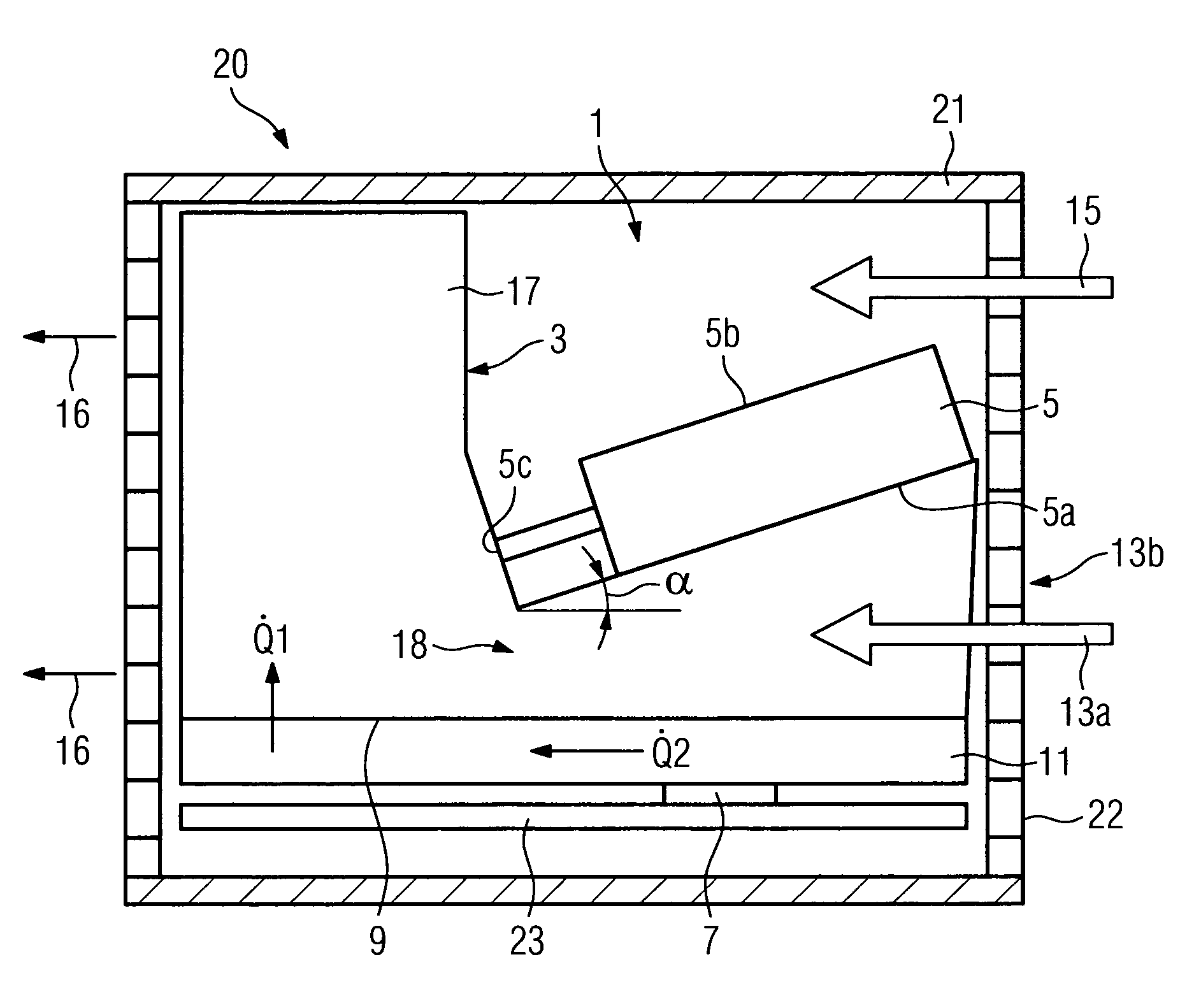
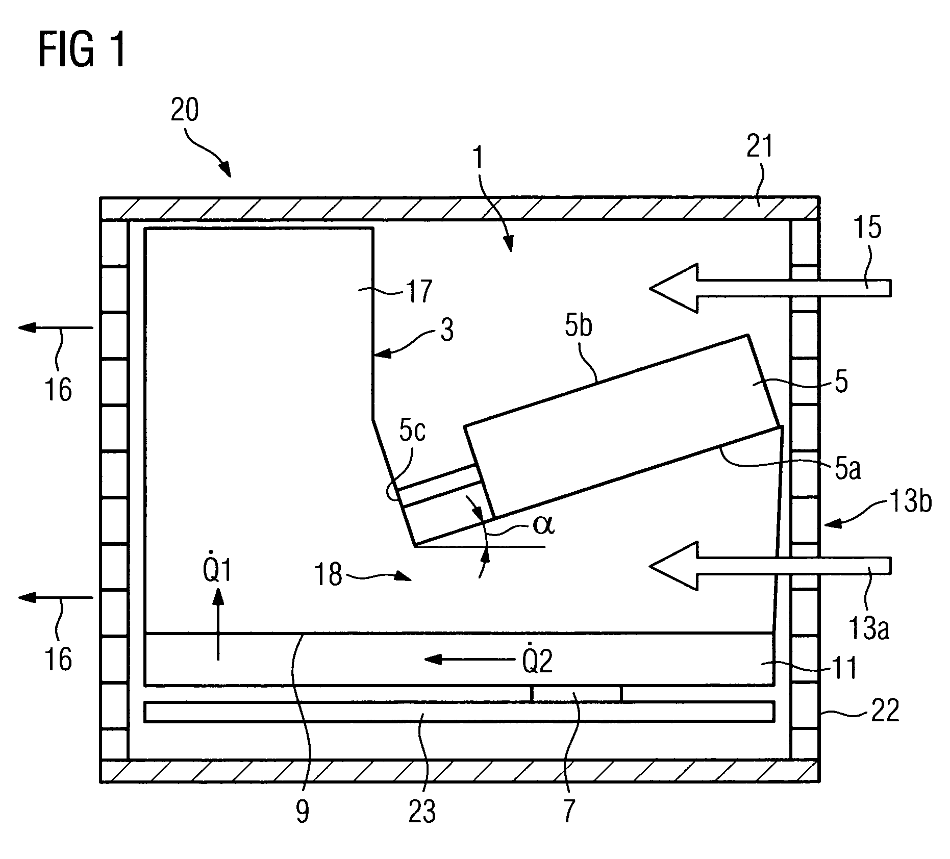
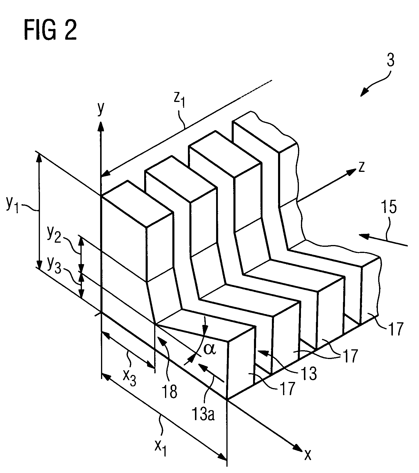
[0025]In accordance with FIG. 1 a module 20 with a cooling facility 1 arranged within a housing 21 is shown viewed from the side without a side cover. The cooling facility 1 features a heat sink 3 and a jet cooler 5 with an underside 5a and an upper side 5b. The heat sink 3 is arranged on a base plate 11. This base plate 11 is thermally connected to a component 7. The component 7 is arranged on a circuit board 23. Microprocessors of CPU modules are usually cooled with these types of cooling facilities 1. The heat sink 3 is essentially embodied as a cuboid shape with a plurality of cooling fins 17 and a recess for accepting the jet coolers 5 within the space which is formed by the maximum three-dimensional measurements of the heat sink. The cooling fins 17 which are arranged in a section for a main flow 13a underneath on the underside 5a of the jet cooler 5 are at an angle α of 20 degrees to the base plate 11 or to the surface 9 of the heat sink 3. The jet cooler 5 is arranged on the...


PUM


Abstract

A heat sink for cooling a component is disclosed. A medium flows around the heat sink by at least sectional guidance of a main flow and a secondary flow of the medium, the main flow being separated from the secondary flow up to a constriction. After the constriction the secondary flow merges with the main flow.

Description

CROSS REFERENCE TO RELATED APPLICATIONS[0001]This application claims priority of European Patent application No. 08004683.2 EP filed Mar. 13, 2008, which is incorporated by reference herein in its entirety.FIELD OF INVENTION[0002]The invention relates to a heat sink for cooling a component, with a medium able to flow around the heat sink. In addition the invention relates to a cooling facility for cooling a component. The invention also relates to an electronic module with a housing and a cooling facility.BACKGROUND OF INVENTION[0003]A significant factor in the use of electronic devices, e.g. CPU modules of automation systems, is the volume required to house the device and the resultant device dimensions. With small device dimensions greater attention must be paid to cooling down the electrical components arranged on the device. In addition shorter processing times of CPU modules in automation systems are demanded, which in its turn results in a higher clock frequency of microproces...

Claims


Application Information

Patent Timeline
Patent Type & Authority Patents(United States)
IPC IPC(8): H05K7/20G06F1/20
CPCH01L23/467H01L23/4735H01L23/3672H01L2924/0002Y10S165/908H01L2924/00H01L23/4336
Inventor BUSCH, KLAUSSCHARF, CHRISTIANWIESNER, CHRISTOPH
Owner SIEMENS AG
Why Eureka
Try Eureka