
Broadcast receiver and method and apparatus for computing viewing/listening information

a receiver and information technology, applied in broadcast services, two-way working systems, broadcast services for monitoring/identification/recognition, etc., can solve the problems of poor response rate, lack of accuracy of survey results, and inability to install back-channel transmitting devices on small receivers such as portable receivers, so as to reduce the burden on the audience member, accurately detect the reception state of the program, and eliminate the need for expensive equipment

Inactive Publication Date: 2010-12-28
SONY CORP
View PDF23 Cites 4 Cited by
  • Summary
  • Abstract
  • Description
  • Claims
  • Application Information

AI Technical Summary

Benefits of technology

[0007]Accordingly, it is an object of the present invention to accurately detect program reception states of a large number of audience while reducing the burden on the audience members and the cost and to strongly encourage the production of programs which reflect audience members' preferences.
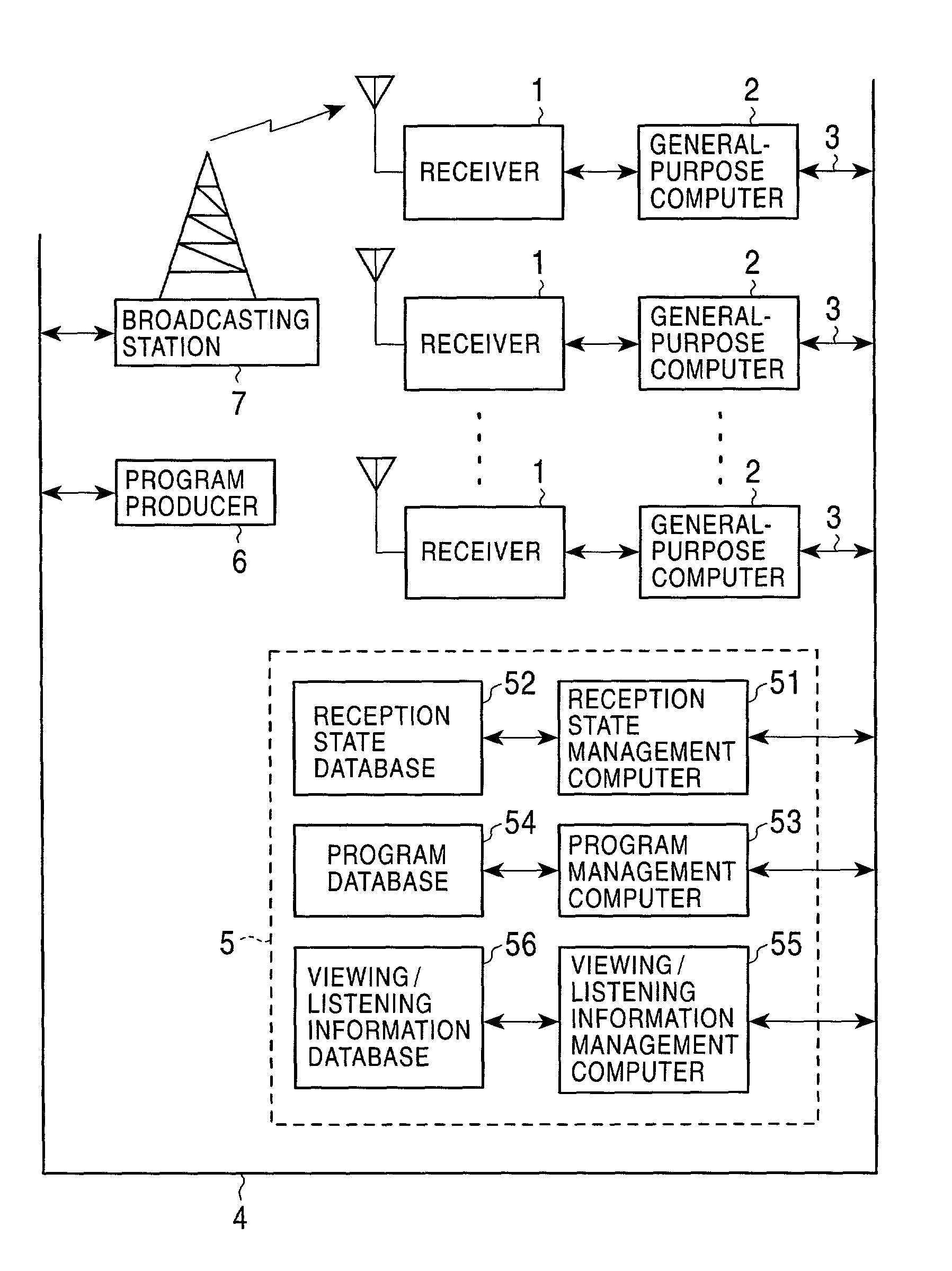
[0012]Accordingly, a broadcast receiver is only required to contain a storage unit for storing a reception log; an interface for transmitting the reception log to an external computer (instead of the storage unit and the interface, the broadcast receiver can be provided with a mounting section on which a removable storage unit with a computer interface is mounted); and a processing program for detecting the reception log of a receiving unit and for recording the reception log in the storage unit or in the storage unit mounted on the broadcast receiver. Thus, the necessity for expensive equipment is eliminated. An audience member is only required to periodically transmit the reception log recorded in the storage unit of the broadcast receiver or in the removable storage unit mounted on the broadcast receiver over a communication network such as the Internet using an external computer such as a general-purpose (household) computer. As a result, the burden on the audience member is reduced.
[0013]Since a controller of the broadcast receiver detects and records the reception log of the receiving unit, the reception log becomes accurate. Currently, computers such as personal computers have been widely used. It is thus possible to obtain reception logs of a large number of broadcast receivers and accurately detect program reception states of a large number of audience. The production of programs which reflect audience members' preferences can be strongly encouraged.
[0014]According to the present invention, it is possible to accurately detect program reception states of a large number of audience using a method which can be implemented at a small cost with minimal burden on the audience members. Thus the production of programs which reflect audience members' preferences can be strongly encouraged.

Problems solved by technology

The method of requesting that the audience members to feedback their program reception states by postcards and facsimiles imposes heavy burden on the audience members, resulting in poor response rate.
Even if responses are collected from the audience members, whether or not the audience members have actually seen a particular program depends on the audience members' responses, and the survey result lacks accuracy.
The method of installing the back-channel transmitting devices on the receivers of some of the audience members has a demerit in that it is impossible to install back-channel transmitting devices on small receivers such as portable receivers.
Another demerit is that dedicated equipment is required for this method, leading to rising costs.
It is therefore impossible to detect the program reception states of a large number of audience.

Method used


Image

  • Broadcast receiver and method and apparatus for computing viewing/listening information
  • Broadcast receiver and method and apparatus for computing viewing/listening information
  • Broadcast receiver and method and apparatus for computing viewing/listening information

Examples


Embodiment Construction

Embodiment of Broadcast Receiver (FIGS. 1 to 3)

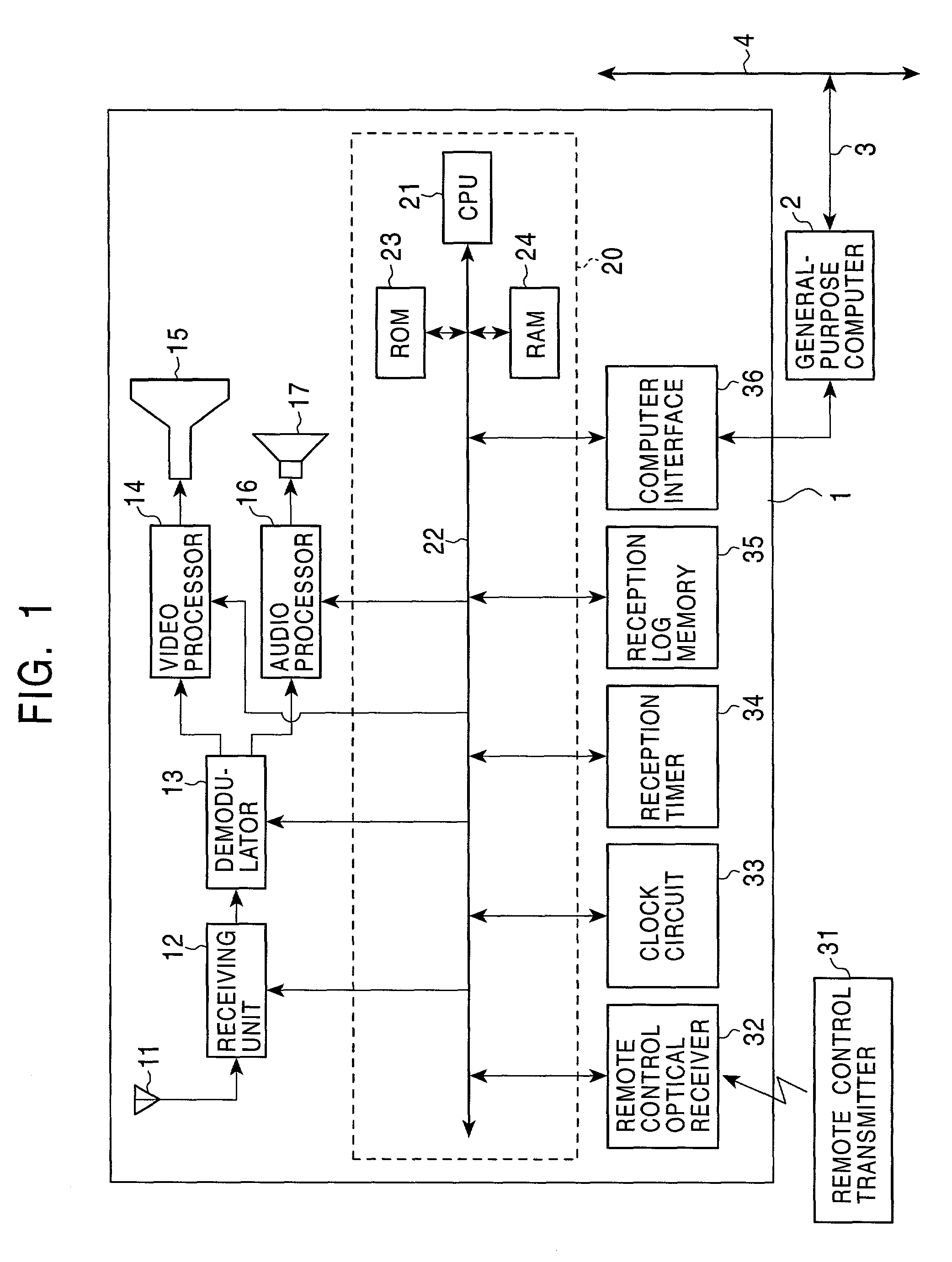
[0022]FIG. 1 shows an example of a broadcast receiver according to an embodiment of the present invention. The broadcast receiver receives terrestrial analog television broadcasting.

[0023]In a receiver 1 in this example, a receiving unit 12 selects a channel and receives airwave signals from an antenna 11. The received signals are demodulated by a demodulator 13. The demodulator 13 generates video signals and audio signals. The video signals are processed by a video processor 14 and output to a display device 15 such as a cathode-ray tube (CRT) display or liquid crystal display (LCD). The audio signals are processed by an audio processor 16 and output to an audio output device 17 such as a loudspeaker or headphone.

[0024]The receiver 1 includes a controller 20 for controlling each portion of the receiver 1 such as channel selection by the receiving unit 12. The controller 20 contains a CPU (central processing unit) 21. A ROM (read only m...


PUM


Abstract

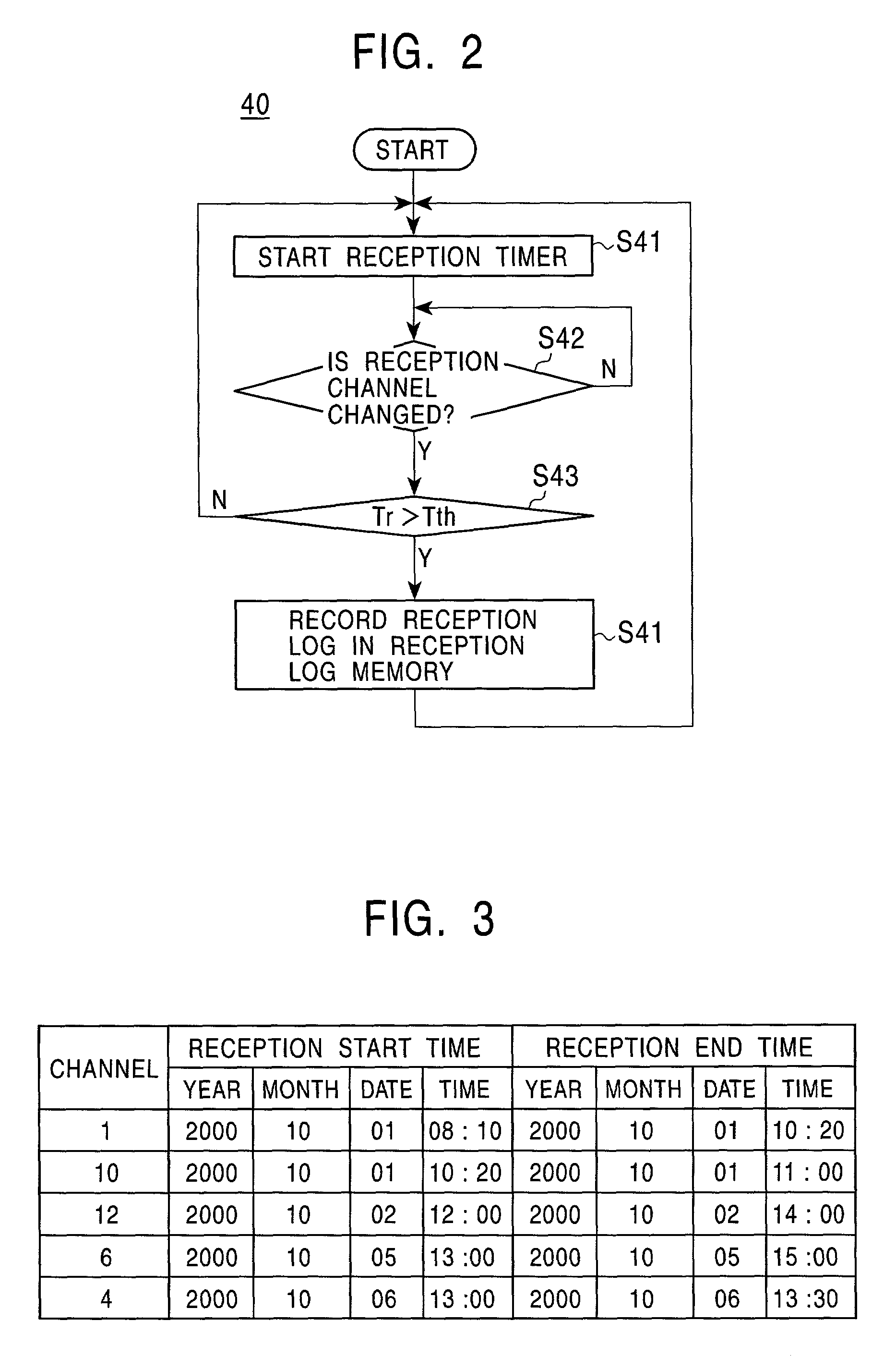
A broadcast receiver includes a controller that detects a reception log of a receiving unit and that records the reception log in a reception log memory. The reception log includes at least the reception channel, reception start time, and reception end time. Periodically an audience member connects the broadcast receiver to a general-purpose computer. The general-purpose computer transmits the reception log data recorded in the reception log memory with a receiver ID written in a ROM through a telephone line over a communication network, such as the Internet. A person who computes viewing / listening information obtains the reception log data and receiver ID from the communication network and computes viewing / listening information, such as a program rating. Instead of providing the broadcast receiver with the reception log memory and a computer interface, a removable storage unit with a computer interface can also be used.

Description

BACKGROUND OF THE INVENTION[0001]1. Field of the Invention[0002]The present invention relates to broadcast receivers and methods and apparatuses for computing viewing / listening-related information such as so-called audience ratings.[0003]2. Description of the Related Art[0004]When broadcasting to the general public, various methods have been employed to survey program reception states of viewers and / or listeners (recipients) at receivers (receiving terminals). Because the receivers are not provided with transmitting functions, the viewers / listeners (hereinafter referred to as “audience members”) are requested to give feedback on their program reception states via postcards, facsimiles, etc. Another example includes a method of installing back-channel transmitting devices on the receivers of some of the audience members and obtaining the program reception states of the receivers through a telephone line.[0005]The method of requesting that the audience members to feedback their progra...

Claims


Application Information

Patent Timeline
IPC IPC(8): H04H60/33H04B1/16H04H20/76H04H60/31H04H60/80H04H60/89H04N5/44H04N17/00
CPCH04H20/76H04H60/31H04H60/66H04H60/80H04H60/89H04H60/37H04H60/39
Inventor KANO, TSUYOSHI
Owner SONY CORP
Learn More