Method and device for making at least partly profiled tubes

a profiled tube and tube body technology, applied in the direction of grooves, metal extrusion, forging hammers, etc., can solve the problems of production machines only suitable and reach their limits on account of dimensions, and achieve space-saving and compact layout of devices

Active Publication Date: 2011-01-04
ERNST GROB
View PDF9 Cites 6 Cited by
  • Summary
  • Abstract
  • Description
  • Claims
  • Application Information

AI Technical Summary

Benefits of technology

[0014]Because the blank is fed by the end of region of the clamping mechanism not subjected to the working process, the length of the mandrel can be chosen to match the length of the region of the blank being worked. In particular, the range of motion of the mandrel can thus be confined practically to the length of the region being worked. The advantage of this is smaller machine dimensions, especially in the area of the drive units and guides. The drive unit of the working station and the rotation drive unit of the mandrel can thus be arranged very compactly on the same machine frame.
[0016]Thanks to the use of a secondary headstock, which is form-fitted to the primary headstock by a lance, one can achieve a very powerful and reliable clamping of the blank for the subsequent working.
[0020]Thanks to a form-fitted and / or frictional connection between the primary headstock and the clamping mechanism, a reliable and precise transmission of the rotary motion of the mandrel to the blank is achieved, which ultimately guarantees high precision of machining.
[0029]Thanks to the invented arrangement of primary headstock, machining station, and secondary headstock, the most space-saving and compact layout of the device is achieved. The machine frame with the machining station and primary headstock integrated on it does not have larger, or even smaller, dimensions than traditional devices, even though it can handle longer machined regions of the blanks or longer blanks. The areas standing off from this machine frame in order to support and guide the secondary headstock are likewise very space-saving and compact, and furthermore can contain the loading and unloading device for the blanks, or leave enough room free for such devices to gain a purchase.

Problems solved by technology

Thus, this traditional method and the corresponding production machines are only suitable for making tubes of a limited length.
If longer tubes need to be made, these production machines reach their limits on account of their dimensions, especially since the mandrel cannot be made arbitrarily longer, due to the higher production costs.

Method used


Image

  • Method and device for making at least partly profiled tubes
  • Method and device for making at least partly profiled tubes
  • Method and device for making at least partly profiled tubes

Examples


Embodiment Construction

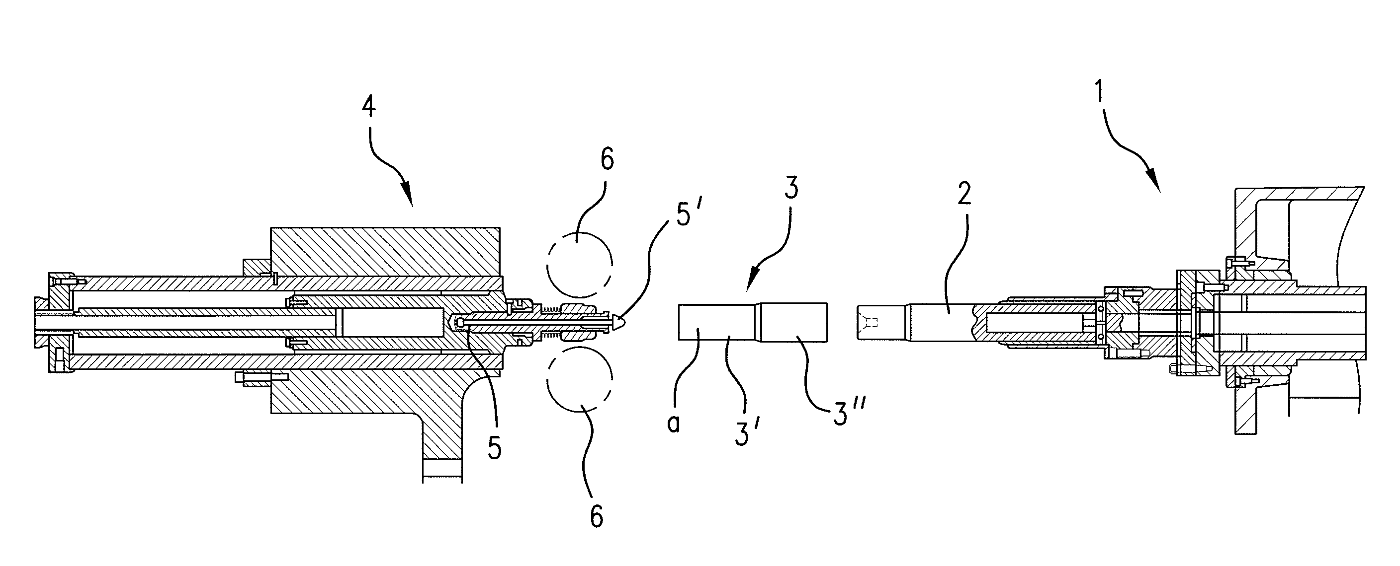
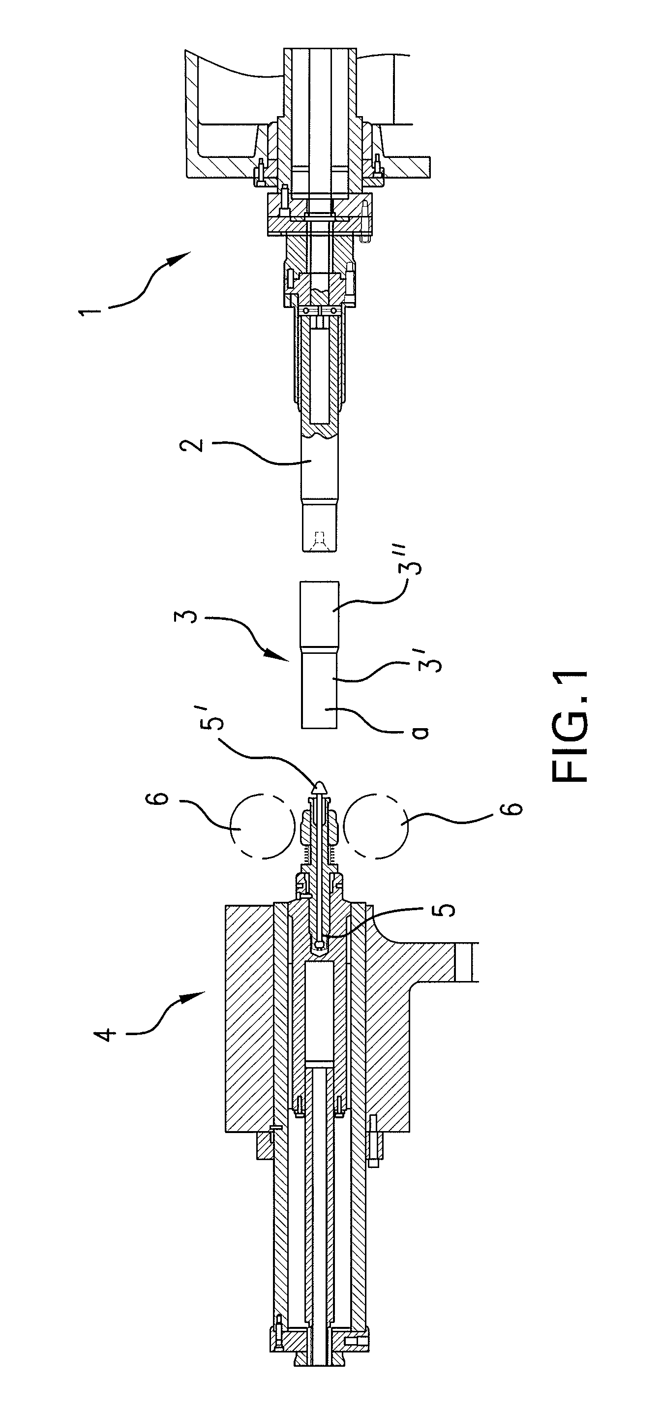
[0039]FIG. 1 shows schematically the layout of a traditional device for making tubes profiled on the inside and outside. The device has, at the right side, a headstock 1 with intermittent rotational drive. To the left of the headstock 1 and protruding there is arranged a mandrel 2, having a surface configured in accordance with the profiling to be imposed on the blank 3.

[0040]The blank 3 has two diameter regions, a first region 3′ with a smaller diameter and a second region 3″ with a larger diameter. The profiling in the example depicted is supposed to be done on region 3″ of the blank 3. Typically, it involves a toothlike profile running parallel to the axis of the blank. Such inside and outside profiled workpieces are used, for example, for two-part telescopic tubes to form telescopic connections in vehicle construction.

[0041]At the left side there is formed a pressure pad 4, having a lengthwise movable spindle sleeve 5. In the area of the resting position of the tip 5′ of the spi...


PUM

PropertyMeasurementUnit
lengthaaaaaaaaaa
outer diameteraaaaaaaaaa

Abstract

A method and device are disclosed for producing tubes that are at least partially profiled on their interior and preferably on their exterior from a hollow cylindrical blank (3), using a mechanical cold forming method, wherein the end of the blank (3) that is not to be machined (3′) is fed to a clamping device (10). The blank (3) is then secured in the clamping device (10) and a mandrel (2) is subsequently inserted into the end of region (3) of the blank (3) that is to be machined. A lance (8) is guided in the mandrel so that it can be coaxially displaced in a longitudinal direction and the free end of the lance (8′) can be introduced into the clamping device (10). The tip (8′) of the lance (8) is then brought into a positive fit with the clamping device (10) in the axial direction of the blank (3) and the mandrel (2), together with the clamping device (10) and the blank (3) is guided axially through a fixed machining point (6). Radial exterior machining of the surface of the blank (3) along the section that is to be machined (3′) takes place at the machining point (6), to create the interior and exterior profiling of the blank (3). During the process, the mandrel (2) is preferably rotated about its axis in an intermittent manner.

Description

RELATED APPLICATION[0001]This application is a U.S. national phase application under 35 U.S.C. §371 of International Application No. PCT / CH2003 / 000601 filed Sep. 5, 2003.TECHNICAL FIELD[0002]The present invention relates to a method for making at least partially profiled tubes, at least on the inside, from a hollow cylindrical blank, as well as a device for carrying out the method.BACKGROUND[0003]Profiled tubes or tube segments are made, for example, in the automotive industry for use as sliding pieces for articulated shafts or movable steering columns. As a rule, two tubes are always used, which can slide lengthwise relative to each other, being form-fitted together in regard to rotation about their lengthwise axis. In this way, it is possible to compensate for changes in the interval between the end points of these tubes, while at the same time transmitting a precise rotation. These requirements, as already mentioned, are necessary for both the drive train and the steering in moto...

Claims


Application Information

Patent Timeline
Patent Type & Authority Patents(United States)
IPC IPC(8): B21D41/00B21H7/18B21J5/12
CPCB21H7/187B21J5/12B21K21/16
Inventor GESER, PETER
Owner ERNST GROB
Why Eureka
Try Eureka