Cylinder and piston assemblies for opposed piston engines

a technology of opposed pistons and pistons, which is applied in the direction of machines/engines, mechanical equipment, etc., can solve the problems of limiting the effective pressure of brakes, early failure of wristpins, and engine reachability

Inactive Publication Date: 2011-01-04
ACHATES POWERS INC
View PDF127 Cites 46 Cited by
  • Summary
  • Abstract
  • Description
  • Claims
  • Application Information

AI Technical Summary

Benefits of technology

In an opposed piston engine, a pair of pistons are disposed in opposition in the bore of a cylinder. The cylinder includes first liquid coolant grooves having a first cooling capacity to cool a portion of the cylinder extending from a central portion toward an exhaust port, and second liquid coolant grooves having a second cooling capacity, less than the first cooling capacity, to cool a portion of the cylinder extending from the central portion toward an inlet port.

Problems solved by technology

Nevertheless, Junkers' basic design contains a number of deficiencies.
These compressive forces, coupled with oscillatory motion of the wristpins and piston heating, cause early failure of the wristpins.
Since the temperature of the cylinder / piston interface is principally determined by the heat of combustion, the breakdown temperature of the lubricant imposes a limit on the engine combustion temperature, which, in turn, limits the brake mean effective pressure (BMEP, an indicator of engine power) achievable by the engine.
The combination of the torque imbalance, the wide separation of the crankshafts, and the length of the gear train produces torsional resonance effects (vibration) in the gear train.
A massive engine block is required to constrain the highly repulsive forces exerted by the pistons on the crankshafts during combustion, which literally try to blow the engine apart.
However, even with these improvements, traditional engine construction and conventional cooling prevent Bird's proposed engine from reaching its full potential for simplification and power-to-weight ratio (“PWR”, which is measured in horsepower per pound, hp / lb).
Thermal and mechanical stresses transmitted through the engine block and uneven heating during engine operation cause non-uniform cylindrical distortion of the cylinders.
The cooling system of Bird's engine provides liquid coolant through the cylinder jackets in the engine block, but the system is not adapted to mitigate the non-uniform distortion of the cylinders or to prevent expansion of the piston crowns.
As a consequence, close tolerances cannot be maintained between cylinders and pistons without a high risk of engine damage or early engine failure.
Of course, without close tolerances, it is difficult to provide an effective seal between cylinders and pistons to limit blowby (the escape of gasses past the piston) during engine operation, without the use of piston rings.

Method used


Image

  • Cylinder and piston assemblies for opposed piston engines
  • Cylinder and piston assemblies for opposed piston engines
  • Cylinder and piston assemblies for opposed piston engines

Examples


Embodiment Construction

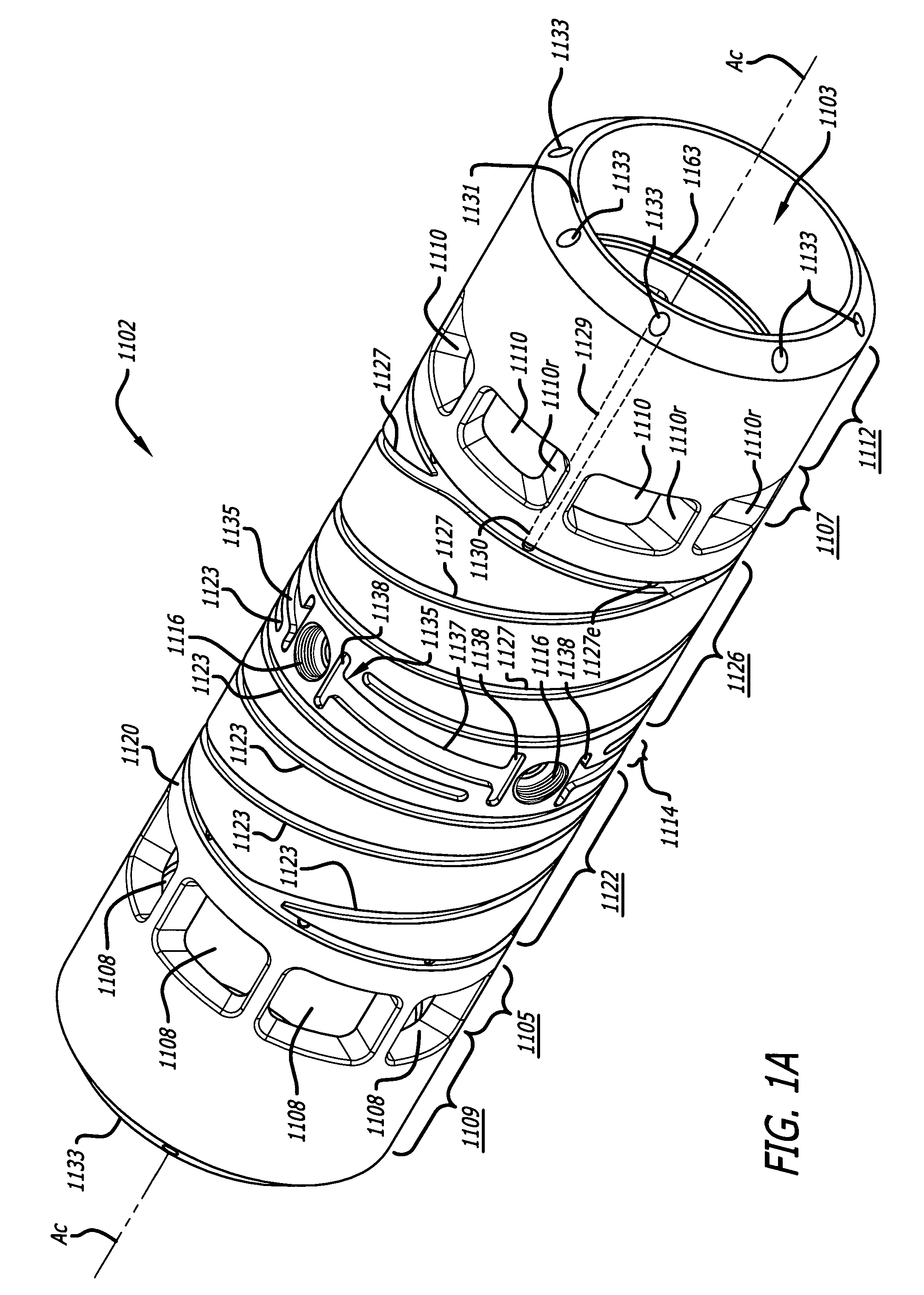
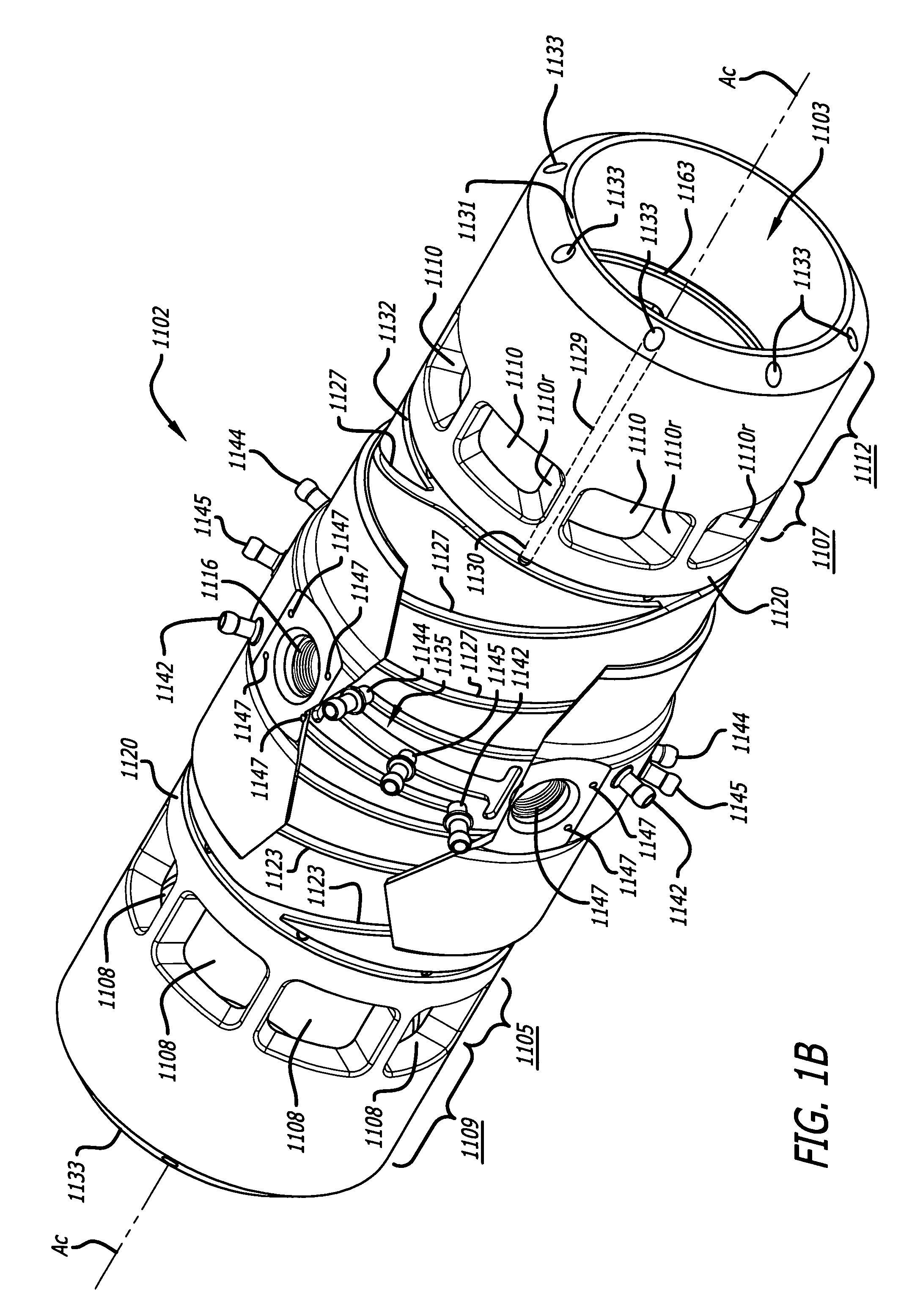
FIGS. 1A-1D illustrate a cylinder 1100 useable in an opposed piston internal-combustion engine. The cylinder 1100 has four parts: a cylinder liner 1102 formed as an open cylindrical tube with a cylindrical bore 1103, an exhaust manifold 1104, an inlet manifold 1106, and a cylinder sleeve 1140. Preferably, the cylinder 1100 is made from aluminum, such as a high-temperature aluminum alloy, and it may be cast or assembled by fixing the manifolds 1104 and 1106 to the cylinder sleeve 1140 and then fixing that subassembly to the outer surface of the cylinder liner 1102. The longitudinal axis Ac of the cylinder liner 1102 is also the longitudinal axis of the cylinder 1100.

As best seen in FIG. 1A, the cylinder liner 1102 has an exhaust port 1105 constituted of a series of circumferentially-spaced openings 1108 near an exhaust end 1109 of the cylinder liner 1102. The cylinder liner 1102 also has an inlet port 1107 constituted of a series of circumferentially-spaced openings 1110 near an inle...


PUM


Abstract

In an opposed piston engine, a pair of pistons are disposed in opposition in the bore of a cylinder. The cylinder includes first liquid coolant grooves having a first cooling capacity to cool a portion of the cylinder extending from a central portion toward an exhaust port, and second liquid coolant grooves having a second cooling capacity, less than the first cooling capacity, to cool a portion of the cylinder extending from the central portion toward an inlet port. Each piston includes a cylindrical skirt with a crown and an open end opposite the crown, a piston rod with a bore, a first end attached to a back surface of the crown, and a second end extending through the open end of the skirt, a radial array of liquid coolant flow passages in communication with the bore and disposed between the first end and the back surface of the crown, and a single wristpin retained on the second end section of the piston rod and positioned externally to the piston.

Description

BACKGROUNDThe invention concerns an internal-combustion engine. More particularly, the invention concerns tailored cooling of the cylinder and pistons of an opposed piston engine.The opposed piston engine was invented by Hugo Junkers around the end of the nineteenth century. Junkers' engine uses two pistons disposed crown-to-crown in a common cylinder having inlet and exhaust ports near bottom-dead-center of each piston, with the pistons serving as the valves for the ports. The engine has two crankshafts, one disposed at each end of the cylinder. The crankshafts, which rotate in the same direction, are linked by connecting rods to respective pistons. Wristpins within the pistons link the rods to the pistons. The crankshafts are geared together to control phasing of the ports and to provide engine output. In a typical Junkers engine, a supercharger is driven from the intake crankshaft, and its associated compressor is used to scavenge the cylinders and leave a fresh charge of air eac...

Claims


Application Information

Patent Timeline
Patent Type & Authority Patents(United States)
IPC IPC(8): F01P1/04F01P1/06F01N13/10F01N13/14F01P3/00F01P3/02F01P3/06F01P3/08F02B75/28F02B75/32F02F1/18F16H1/22
CPCF02B75/28F02B75/282F02B75/32F02F1/186F01P3/06F01P2003/005F01P2003/006F01P2003/021F01P2003/027F01P2003/028F16H1/22F01P3/08F02F1/18
Inventor LEMKE, JAMES U.HOFFMAN, RONALD J.WAHL, MICHAEL H.LEE, PATRICK R.
Owner ACHATES POWERS INC
Why Eureka
Try Eureka