Gas manifold for a cooking range, with a pipe closure

a technology for gas manifolds and cooking ranges, which is applied in the direction of heating fuel, combustion process, domestic heating details, etc., can solve the problems of insufficient weld strength in the central region, the thickness of the closure wall after compacting the metal and the thickness of the closure wall is greater than the original thickness of the pip

Inactive Publication Date: 2011-01-04
COPRECITEC
View PDF53 Cites 54 Cited by
  • Summary
  • Abstract
  • Description
  • Claims
  • Application Information

AI Technical Summary

Benefits of technology

[0006]The object of the invention is a gas manifold fitted with a number of manual taps interspaced along the distributor conduit made of aluminium, or a similar corrosion-resistant alloy and adapted for the supply of a gas flow to a cooking appliance, wherein the opposite end of the pipe is sealed hermetically without addition of metal by means of the radial compaction of the wall of the end of the pipe softened by the friction of at least one rotation tool, wherein the wall of the closure is assured in order to withstand the pressure of the gas flow without any leakage.
[0008]The gastight seal of the pipe end achieved according to the invention, results with a wall thickness greater than that of the original pipe and, in particular, in its central region it is of a thickness considerably greater enlarged with a tip, which withstands the real pressure of the gas flow distributed and assures the tightness in all the pipe closures made.

Problems solved by technology

In the examples quoted from the prior art the resultant thickness of the closure wall after compacting the metal, although greater than the original thickness of the pipe, is not sufficient to assure a weld in the central region without gas leakage.

Method used


Image

  • Gas manifold for a cooking range, with a pipe closure
  • Gas manifold for a cooking range, with a pipe closure

Examples


Embodiment Construction

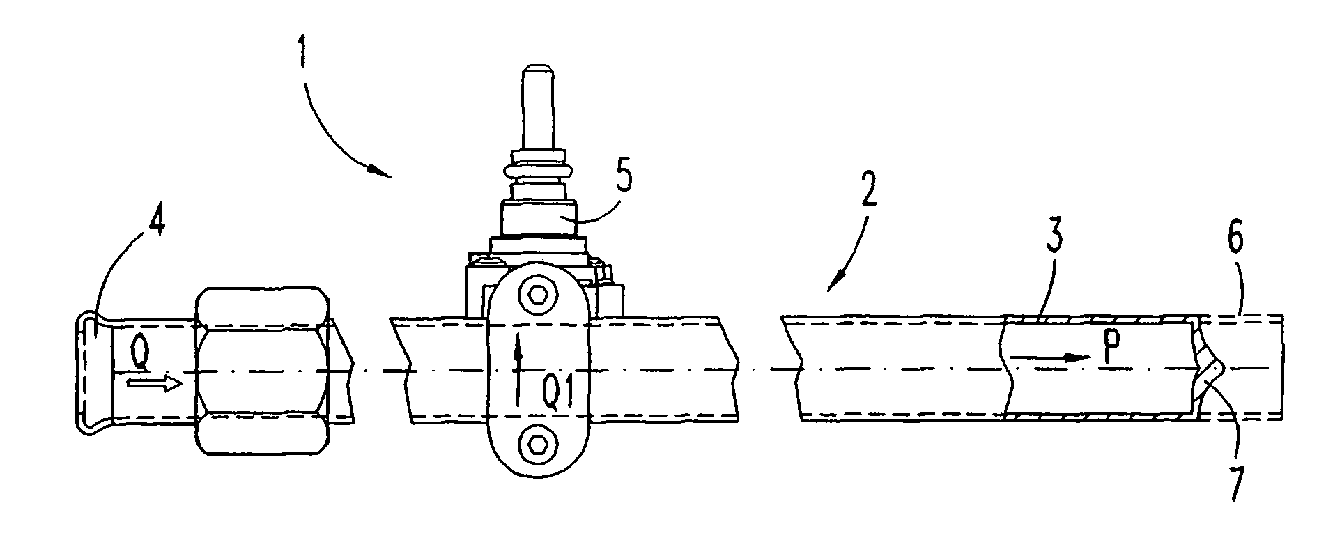
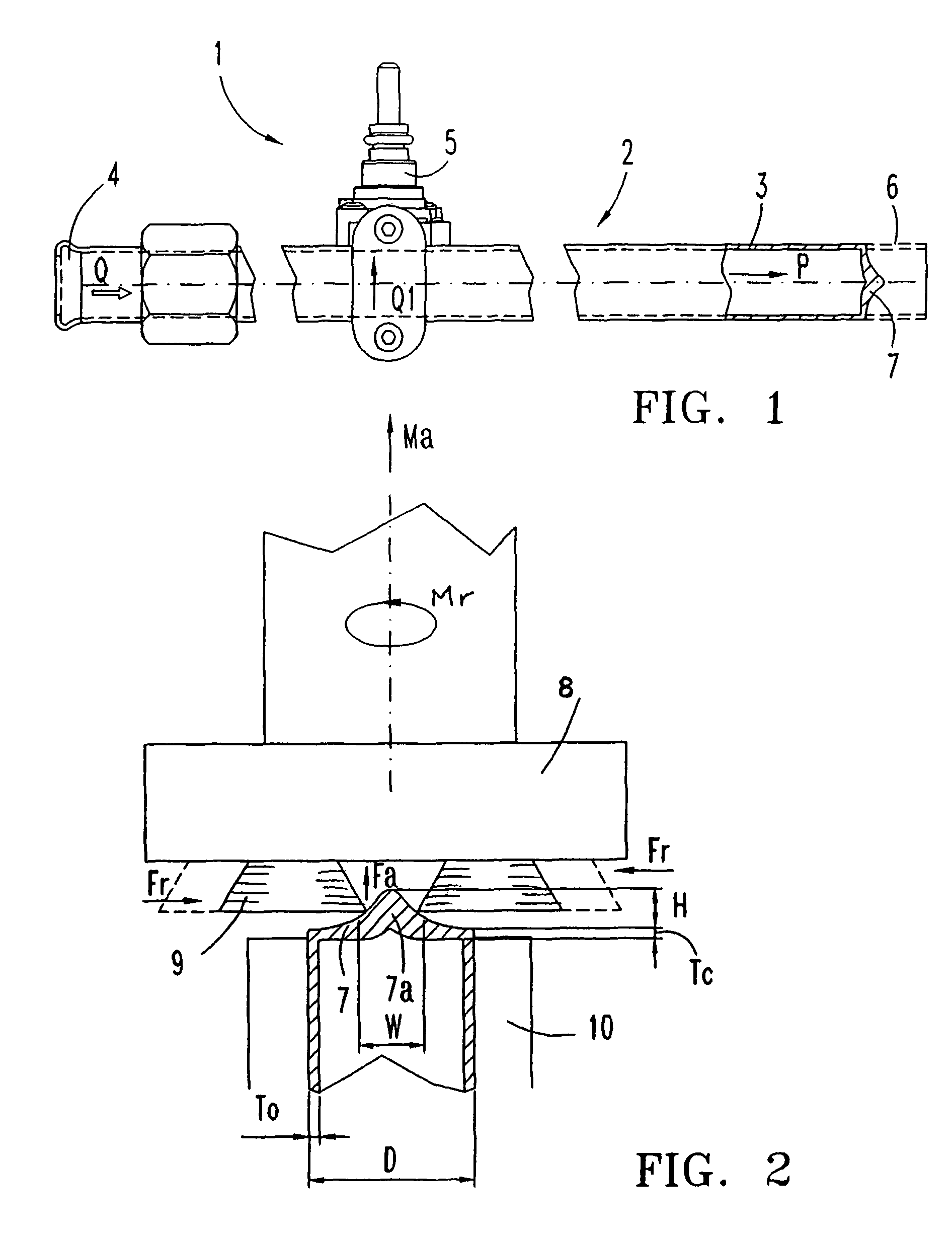
[0011]In reference to FIG. 1 and FIG. 2, an embodiment of gas manifold 1 for installation on a cooking range comprises a distributor conduit 2 made by means of a long, thin-wall alloy pipe 3, preferably of cylindrical cross section, with an open end 4 of the conduit for the intake of a flow Q for the gas supply of the cooking range at a pressure “P”, a number of regulating taps 5 which distribute the partial flows Q1 supplied to the range and an end 6 of the pipe with an end closure 7, which has been formed for safety against leakage of gas of said flow Q at pressure “P”. A cylindrical pipe 3 is made in particular of an alloy with a low softening temperature such as aluminium or corrosion-resistant aluminized steel. The pipe 3 is chosen of a diameter “D” in keeping with the regulating tap model 5 and its fastening to the distributor conduit 2. For economic reasons the thinnest possible original pipe wall thickness “To” is chosen, capable of conferring on pipe 3 the strength necessar...


PUM

PropertyMeasurementUnit
thicknessaaaaaaaaaa
width dimensionaaaaaaaaaa
height dimensionaaaaaaaaaa

Abstract

The gas manifold (1) adapted for installation on a cooking range includes a conduit (2) for distribution of a flow (Q) at a pressure “P”, with a number of regulating taps (5) fixed to the conduit (2). The conduit is made from a metal pipe (3) with a thin cylindrical wall To and the pipe end (6) is sealed without cracks by means of friction welding with no addition of material, with a sealing wall (7) formed by means of a thickening in the form of a tip (7a) in the axial direction of an enlargement or height “H” greater than the original thickness To of the pipe. For making the gastight closure a rotary tool (8) is used that includes at least two rotary rollers (9) for the compaction of the metallic mass between two counterposed centripetal forces (Fr), in combination with an axial stretching force (Fa).

Description

[0001]The present invention relates to a gas manifold with a number of regulating taps installed on a flow distributor pipe, wherein one of the ends of the manifold pipe is sealed hermetically.PRIOR ART[0002]Fuel gas manifolds fitted with rotary type manual taps are already known. They are installed on a panel of the frame of the cooking appliance with the control shafts of the taps aligned on a front panel of the cooking appliance. One of the ends of the manifold pipe is open for the connection of a hose for the supply of the fuel gas to the manifold, while the opposite end is sealed hermetically to prevent any leakage of gas. The gas flow manifold is preferably made of a long thin-wall pipe, made of aluminium or steel alloy with corrosion-resistant aluminium. The thinnest possible thickness of the wall on each of the pipes is determined in accordance with the strength required for handling and / or the strength necessary for machining and connection of the taps to the manifold condu...

Claims


Application Information

Patent Timeline
Patent Type & Authority Patents(United States)
IPC IPC(8): F24C3/00
CPCF24C3/12B21D41/045B21J5/063B21K21/14F23K2300/20F23K2300/206
Inventor BELLOMO, ALBERTO
Owner COPRECITEC
Why Eureka
Try Eureka