Electromechanical door solenoid current surge booster circuit

a technology of current surge booster and door solenoid, which is applied in the direction of magnets, mechanical devices, magnetic bodies, etc., can solve the problems of inconvenient installation of heavy gauge wiring to carry current between the power supply and the door solenoid, affecting the operation of the door solenoid, and requiring a substantial momentary current load. to achieve the effect of reducing the current capacity

Active Publication Date: 2011-01-04
COMMAND ACCESS TECH
View PDF3 Cites 31 Cited by
  • Summary
  • Abstract
  • Description
  • Claims
  • Application Information

AI Technical Summary

Benefits of technology

[0015]A solution to the above has been devised. The power supply is located on one end of the transmission wire and a capacitor connected to the solenoid is located on the other end of the transmission wire, adjacent to the door latching mechanism. The capacitor provides a current reserve that may be drawn on when the primary coil is activated, greatly reducing the current capacity needed to be carried over the transmission wire. This current boost by the capacitor allows sufficient additional current to be delivered to the solenoid to momentarily operate the primary coil to move the latching mechanism from a locked to an unlocked position.
[0016]In the preferred embodiment the booster circuit of the present invention includes the capacitor and circuitry to monitor voltage in the system and to time and switch the primary coil on and off. The booster circuit is located on the door, close to or directly adjacent the solenoid. The problem of voltage drop due to the distance between the power supply and solenoid is thus reduced.
[0017]The use and placement of a booster circuit in this manner decreases the need for heavier gauge wiring and to have the power supply located so close to the door. Because the power supply may be located at a greater distance from the latching mechanism a wider variety of design choices is allowed for placing the power supply. Voltage drop is much less of a problem because the transmission line current load is less. The capacitor and secondary coil are charged with a relatively steady current from the power supply and the secondary coil only draws about half an ampere. The power supply and transmission wire then need only be suitable for carrying current sufficient to charge the capacitor and power the secondary coil.
[0023]This construction allows for door latching operation without the need for a higher capacity power supply that must be in such close proximity to the latching mechanism and without the need for the use of a larger gauge transmission wire. The use of the present invention allows the power supply to be placed at much greater distances from the latching mechanism, perhaps 250 feet, allowing a wider choice of power supply locations. The elimination of the need for heavier gauge wiring is particularly useful for retrofitting electromechanical door latching devices in existing buildings because existing smaller transmission wire may be used.

Problems solved by technology

The solenoids used with these devices require a substantial momentary current load for an interval of time to move the latching mechanism.
A longstanding problem with the prior art is that the power supply for the latching mechanism must be able to supply power at an acceptably safe lower voltage and with sufficient current to meet the inrush surge current load drawn during actuation of the primary coil of the solenoid.
Typically the transmission wire connecting the power supply to the door latch solenoid cannot exceed more than twenty-five feet in length and therefore presents an inherent design limitation.
Standard 18-gauge electrical wiring used in buildings is usually unsuitable for carrying the needed momentary current surge load between the power supply and the solenoid of a door latch mechanism so heavier gauge wiring, 12-gauge wire for example, is typically used instead.
The need to install heavier gauge wiring to carry current between the power supply and the door solenoid is costly and laborious.

Method used


Image

  • Electromechanical door solenoid current surge booster circuit
  • Electromechanical door solenoid current surge booster circuit
  • Electromechanical door solenoid current surge booster circuit

Examples


Embodiment Construction

[0032]The following detailed description, and the figures to which it refers, are provided for the purpose of describing example(s) and specific embodiment(s) of the invention only and are not intended to exhaustively describe all possible examples and embodiments of the invention.

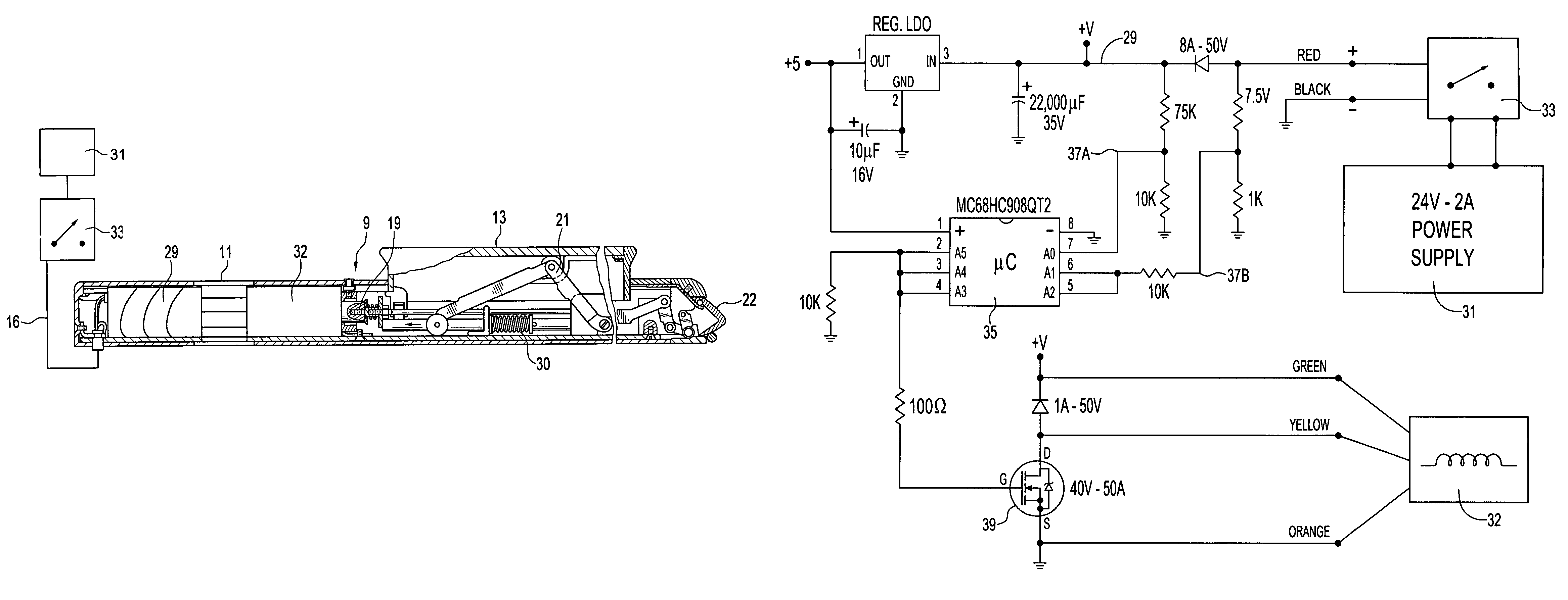
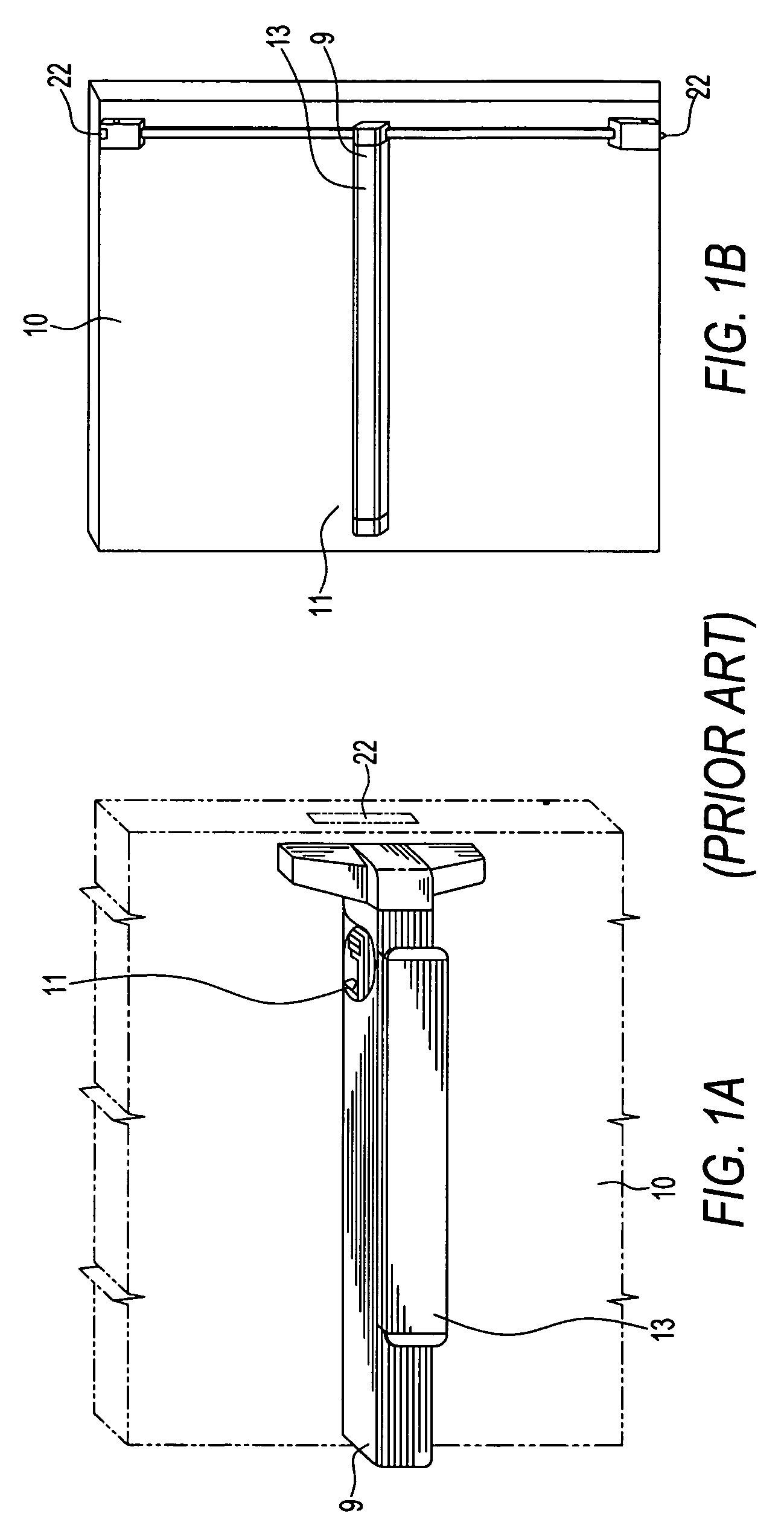
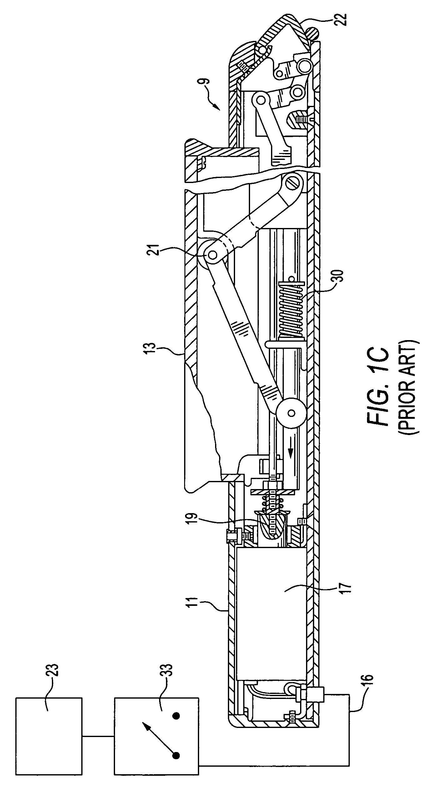
[0033]Referring now to FIGS. 1A, 1B and 1C front and schematic views are shown of the general attributes of typical latching devices of the prior art with which the present invention may be used. FIG. 1A is a view of a mortise type latching mechanism actuated by a touch plate that is mounted on a portion of a door; FIG. 1B is a view of a vertical rod type of latching mechanism. FIG. 1C is a side schematic view of a rim type latching mechanism. These different types of door latching mechanisms are presented by way of example to display the variety of latching mechanisms used and not so as to limit the scope of the invention. The present invention may be used with other electromechanical door latching config...


PUM


Abstract

An apparatus, circuit and method for operating a solenoid-actuated electromechanical door latching mechanism that includes a capacitor to meet the power surge requirements needed to move a door latching mechanism. A power supply at one end of a transmission line is coupled with a capacitor adjacent the solenoid at the other end of the transmission line to reduce the need for a larger capacity power, heavy gauge transmission lines and increases the distance at which a power supply may be located from a door latching device.

Description

CROSS REFERENCE TO RELATED APPLICATION[0001]This patent application claims priority to U.S. Provisional Patent Application No. 60 / 618,019 filed on Oct. 12, 2004, entitled Electromechanical Door Solenoid Current Surge Booster Circuit, which is incorporated herein by reference.FIELD OF THE INVENTION[0002]This invention relates to electromechanical door opening devices and more particularly to a method and apparatus for a supplying power to an electromechanical door latch actuator.BACKGROUND OF THE INVENTION[0003]Electromechanical security door lock mechanisms actuated by solenoids are ubiquitous. A typical lock mechanism allows a user on one side of a door to mechanically actuate the locking mechanism to release the lock while requiring a user on the other side of the door to actuate it electromechanically with a security device such as a key, a card reader, or a keypad requiring that a password, number or word be entered.[0004]Panic exit devices, for example, employ a mechanical latc...

Claims


Application Information

Patent Timeline
Patent Type & Authority Patents(United States)
IPC IPC(8): E05B65/10
CPCE05B47/023E05B65/1053E05B47/0002E05B65/1093E05B2047/0054E05B2047/0057H01F7/1816Y10T292/0909Y10T292/1021Y10T292/1082
Inventor ESCOBAR, MIGUEL A.
Owner COMMAND ACCESS TECH
Why Eureka
Try Eureka