Cutting tool with multiple flutes defining different profiles, and method

a technology of cutting tools and profiles, applied in the field of cutting tools, can solve the problems of thermal expansion or deformation time-consuming and resource-consuming, and substantial forces, and achieve the effect of reducing the thermal expansion of tools and workpieces

Active Publication Date: 2011-01-04
SECO TOOLS AB
View PDF26 Cites 39 Cited by
  • Summary
  • Abstract
  • Description
  • Claims
  • Application Information

AI Technical Summary

Benefits of technology

[0004]It is desirable to provide a cutting tool that is useful for forming complex shapes yet can do so without the need for generating high forces and can minimize thermal expansion of tool and workpiece during machining.

Problems solved by technology

This can be done in a plurality of operations, often with different tools, which can be time- and resource-consuming.
A drawback of such tools is that substantial forces are generated as the cutting edges cut through the workpiece.
The high forces can deform the tool and generate substantial heat, which heat can result in thermal expansion or deformation of the tool and the workpiece, leading to inaccurate cutting or formation of burrs which must be removed in a subsequent operation.

Method used


Image

  • Cutting tool with multiple flutes defining different profiles, and method
  • Cutting tool with multiple flutes defining different profiles, and method
  • Cutting tool with multiple flutes defining different profiles, and method

Examples


Embodiment Construction

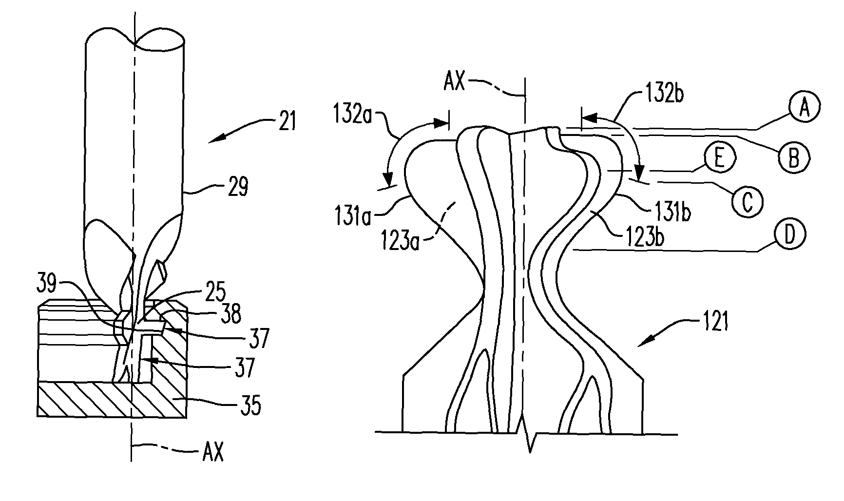
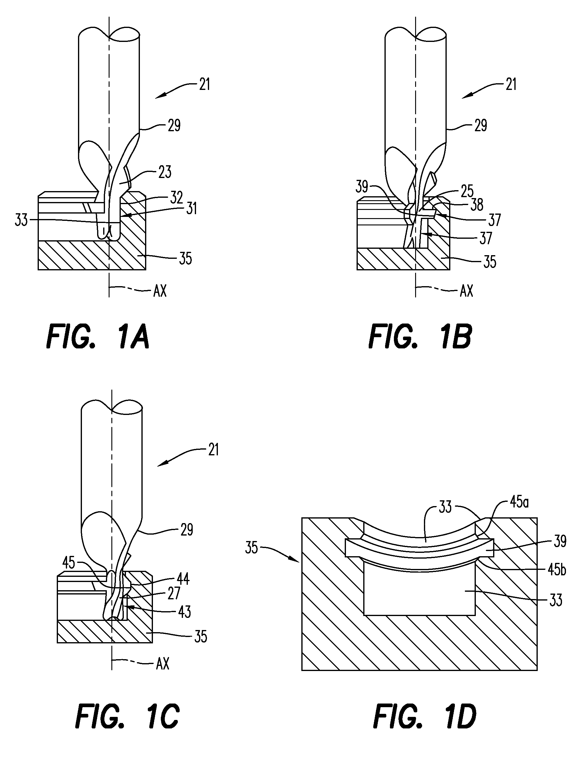
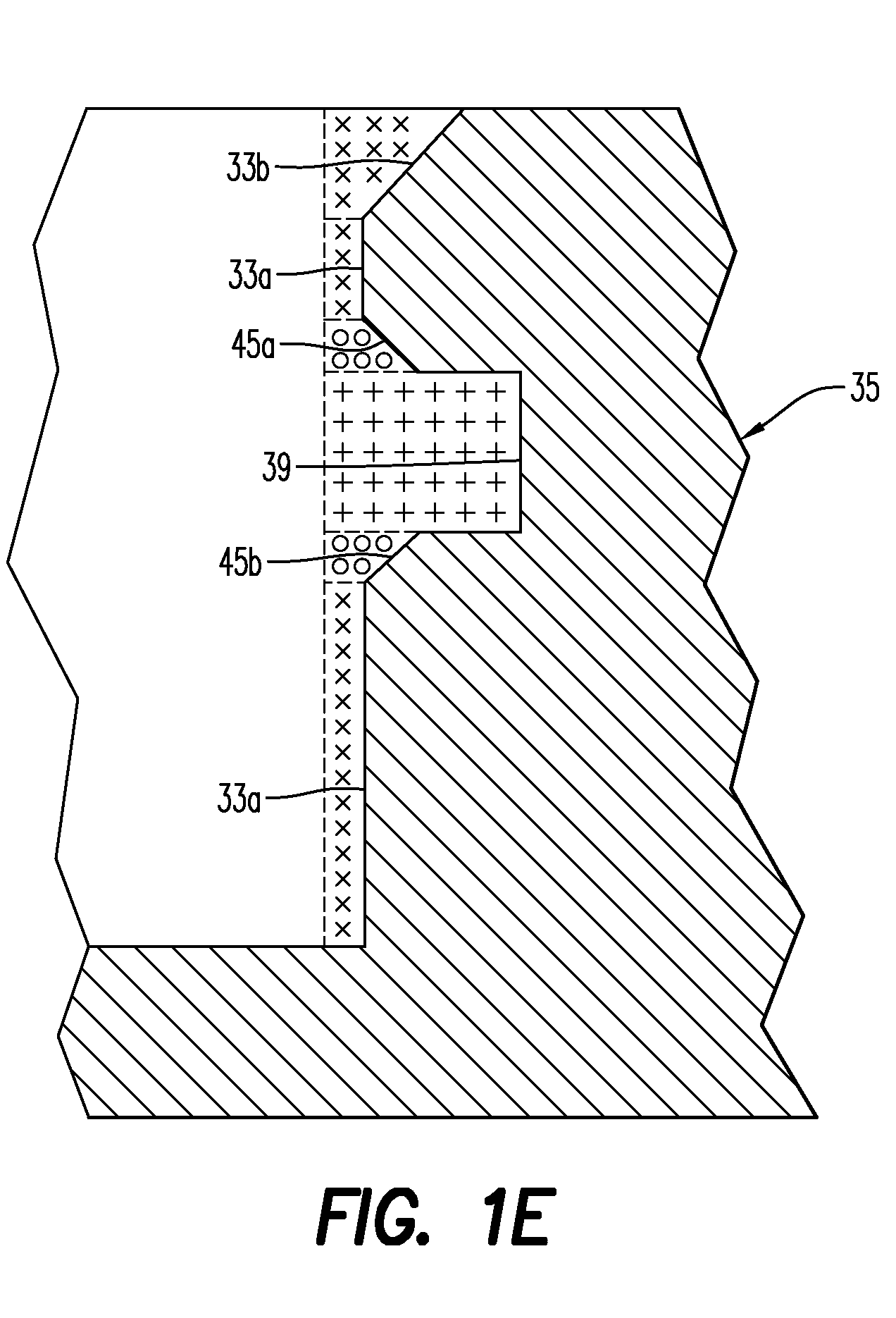
[0012]A cutting tool 21 is shown in FIG. 1A-1C having at least two flutes, here shown having three flutes 23, 25, and 27. The cutting tool 21 includes a tool body 29 having a longitudinal axis AX. The flutes 23, 25, and 27 are provided in the body 29 of the cutting tool 21.

[0013]As seen in FIG. 1A, a first flute 23 comprises a first leading edge 31 that defines a first profile 32 for forming a first shape 33 in a workpiece 35, the first shape corresponding to the first profile, when the first leading edge is rotated about the longitudinal axis AX. For purposes of the present application, the “profile” of the leading edge of a flute will be defined as that portion of the leading edge that performs a cutting operation to form a particular shape, i.e., a working portion of the leading edge. A second flute 25 comprises a second leading edge 37 that defines a second profile 38 for forming a second shape 39 in the workpiece as seen in FIG. 1B, the second shape corresponding to the second ...


PUM

PropertyMeasurementUnit
radiiaaaaaaaaaa
cutting forcesaaaaaaaaaa
lengthaaaaaaaaaa

Abstract

A cutting tool having multiple cutting edges includes a tool body having a longitudinal axis, a first cutting edge including a first leading edge that defines a first profile when rotated about the longitudinal axis, and a second cutting edge including a second leading edge that defines a second profile when rotated about the longitudinal axis, the first and second profiles being different from each other and being adapted to cut a workpiece in succession. A method is also disclosed.

Description

BACKGROUND AND SUMMARY[0001]The present invention relates to cutting tools and, more particularly, to cutting tools with multiple flutes defining different profiles.[0002]In machining operations such as milling, it is frequently necessary to form a plurality of shapes such as grooves, chamfers, and the like in a workpiece. This can be done in a plurality of operations, often with different tools, which can be time- and resource-consuming. Often, dedicated tools with cutting edges provided to form the desired shapes in the workpiece are provided. For example, dedicated tools with specific shapes are often used in forming root slots in Titanium disks as used in the compressor section of a turbine. Dedicated tools are also often employed in machining complex shapes such as when machining Ultra High Density Polyethylene (UHDPE).[0003]A drawback of such tools is that substantial forces are generated as the cutting edges cut through the workpiece. The high forces can deform the tool and g...

Claims


Application Information

Patent Timeline
Patent Type & Authority Patents(United States)
IPC IPC(8): B23C5/12
CPCB23C5/10B23C2210/084B23C2210/086B23C2210/285B23C2210/287Y10T407/196B23C2226/61Y10T407/1962Y10T29/49996Y10T407/1948B23C2210/325B23C3/28B23C5/12
Inventor VAN IPEREN, JAN-WILLEM
Owner SECO TOOLS AB
Why Eureka
Try Eureka