

Flinger disc
a technology of flinger discs and flinger discs, which is applied in the direction of drip or splash lubrication, machines/engines, transportation and packaging, etc., can solve the problems of premature wear and component or system failure, premature wear or even failure of machine elements, and the diameter of traditional flinger discs is limited, so as to reduce the temperature, increase the life of bearings, and increase the lubrication life
- Summary
- Abstract
- Description
- Claims
- Application Information
AI Technical Summary
Benefits of technology
Problems solved by technology
Method used
Image

Examples
Embodiment Construction
[0026]Although the disclosure hereof is detailed and exact to enable those skilled in the art to practice the invention, the physical embodiments herein disclosed merely exemplify the invention which may be embodied in other specific structure. While the preferred embodiment has been described, the details may be changed without departing from the invention.
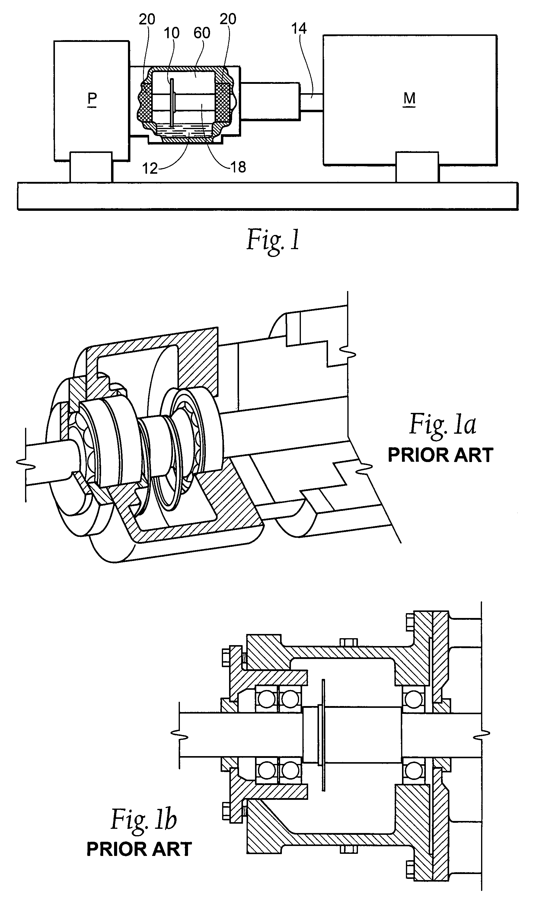
[0027]Referring now to FIG. 1, a side view, with portions broken away, of the workpiece to which the flinger disk of the present invention is advantageously applied is shown, although the invention can be applied in different work environs. In FIG. 1, the workpiece is shown as a centrifugal pump P with a motor M. The invention provides an optimal lubrication condition to machine element or bearings 20 by providing a flinging of the lubricant 12, such as oil. In FIG. 1, the bearings 20 are viewed from the side, with their front profile generally doughnut shaped. The lubricant 12 is contained within a fluid reservoir, or bearing ho...
PUM
 Abstract
Description
Claims
Application Information