Battery residual quantity display method and electronic equipment

a residual quantity and display method technology, applied in the field of battery residual quantity display method, can solve the problems of equipment body breakage/damage, etc., and is impossible to perform other processing, so as to reduce the cost of hardware, reduce the development cost of software, and reduce the effect of cos

Inactive Publication Date: 2011-01-04
SONY CORP
View PDF20 Cites 1 Cited by
  • Summary
  • Abstract
  • Description
  • Claims
  • Application Information

AI Technical Summary

Benefits of technology

[0011]In view of the above, an object of the present invention is to provide a battery residual quantity display method and an electronic equipment, which are capable of providing both functions of battery residual quantity display and battery authentication processing without increasing load of the microcomputer.
[0014]In the present invention, authentication of the battery is performed to thereby make it impossible to use coarse battery at the set (equipment body), thus making it possible to prevent, in advance, breakage / damage, etc. of equipment body by use of the battery except for normal or genuine battery.
[0016]Further, in the present invention, battery residual quantity display processing and battery authentication processing are performed within the same system so that there is no necessity of independently having signal lines between the set and the battery. As a result, reduction of the cost of the hardware can be realized. Further, since it is sufficient to provide communication driver of one system, development cost of the software can be reduced.
[0017]Furthermore, in the present invention, the battery authentication processing is divided to perform battery authentication processing in the middle of the residual quantity display processing of the battery so that not only it becomes difficult that a bad-will person such as maker, etc., who prepares coarse battery analyzes a way of performing authentication, but also battery authentication can be performed even if high performance microcomputer is not used. For this reason, the cost is reduced. Further, since battery authentication can be performed even if the microcomputer is not used at a high speed, the power consumption can be reduced.
[0018]In addition, in the present invention, since battery authentication result is stored, user can concentrate on battery residual quantity display processing at the second time operation when power is turned ON and operations subsequent thereto. Thus, direct merit with respect to user can be protected.

Problems solved by technology

When battery pack dedicated for corresponding equipment is not used, there results a cause to lead breakage / damage, etc. of the equipment body.
Moreover, hitherto, in the case of performing communication of information between charging unit and control means within mobile information processing apparatus to perform authentication of battery, authentication processing of battery is performed prior to other processing so that when battery authentication processing is not completed, it is impossible to perform other processing.

Method used


Image

  • Battery residual quantity display method and electronic equipment
  • Battery residual quantity display method and electronic equipment
  • Battery residual quantity display method and electronic equipment

Examples


Embodiment Construction

[0024]The embodiments of the present invention will now be described in detail with reference to the attached drawings. It should be noted that the present invention is not limited to the embodiments shown below, but it is a matter of course that changes or modifications may be made as occasion demands within the scope of the knowledge that persons ordinarily skilled in the art have within the scope which does not depart from the gist of the present invention.

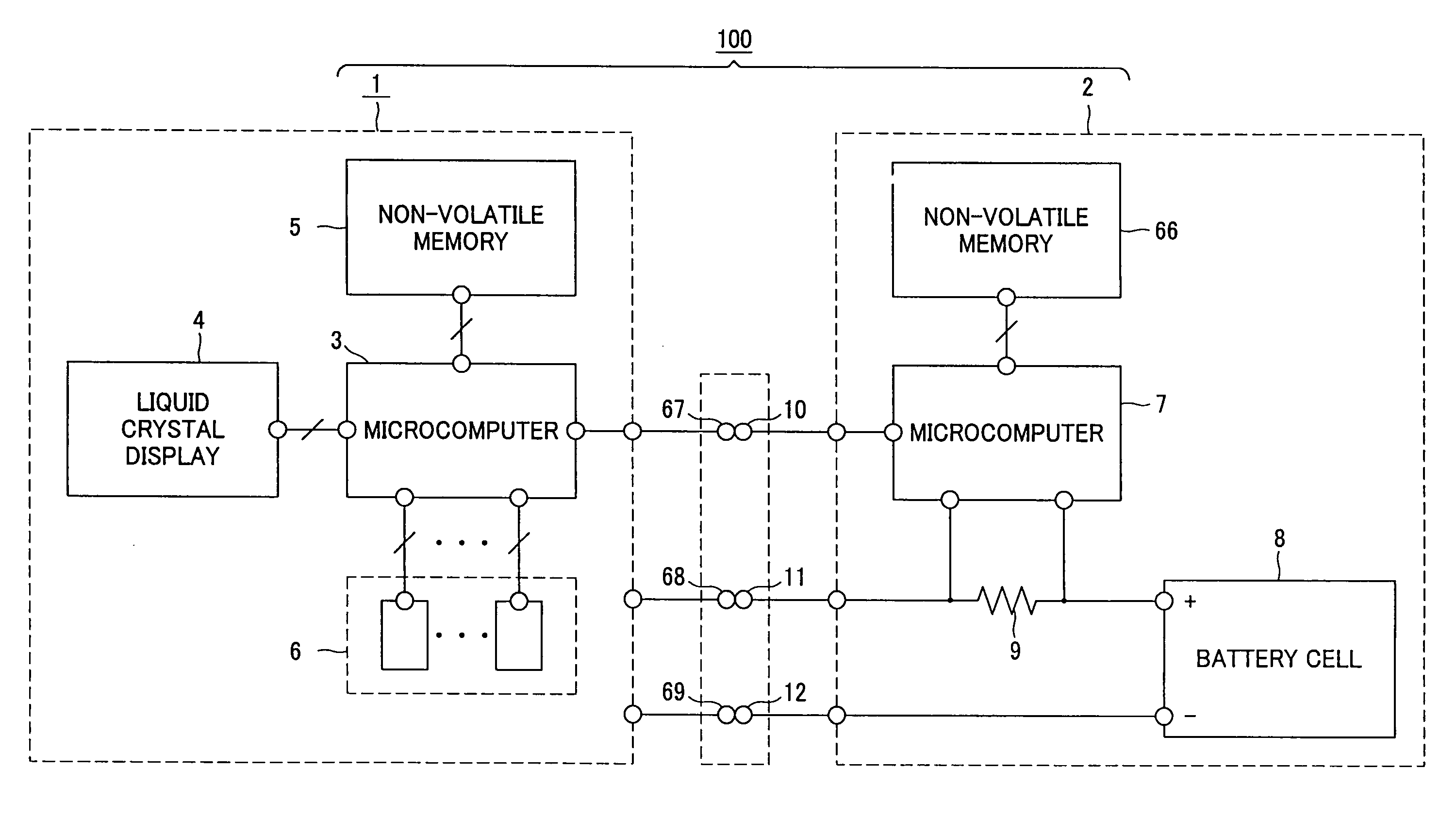
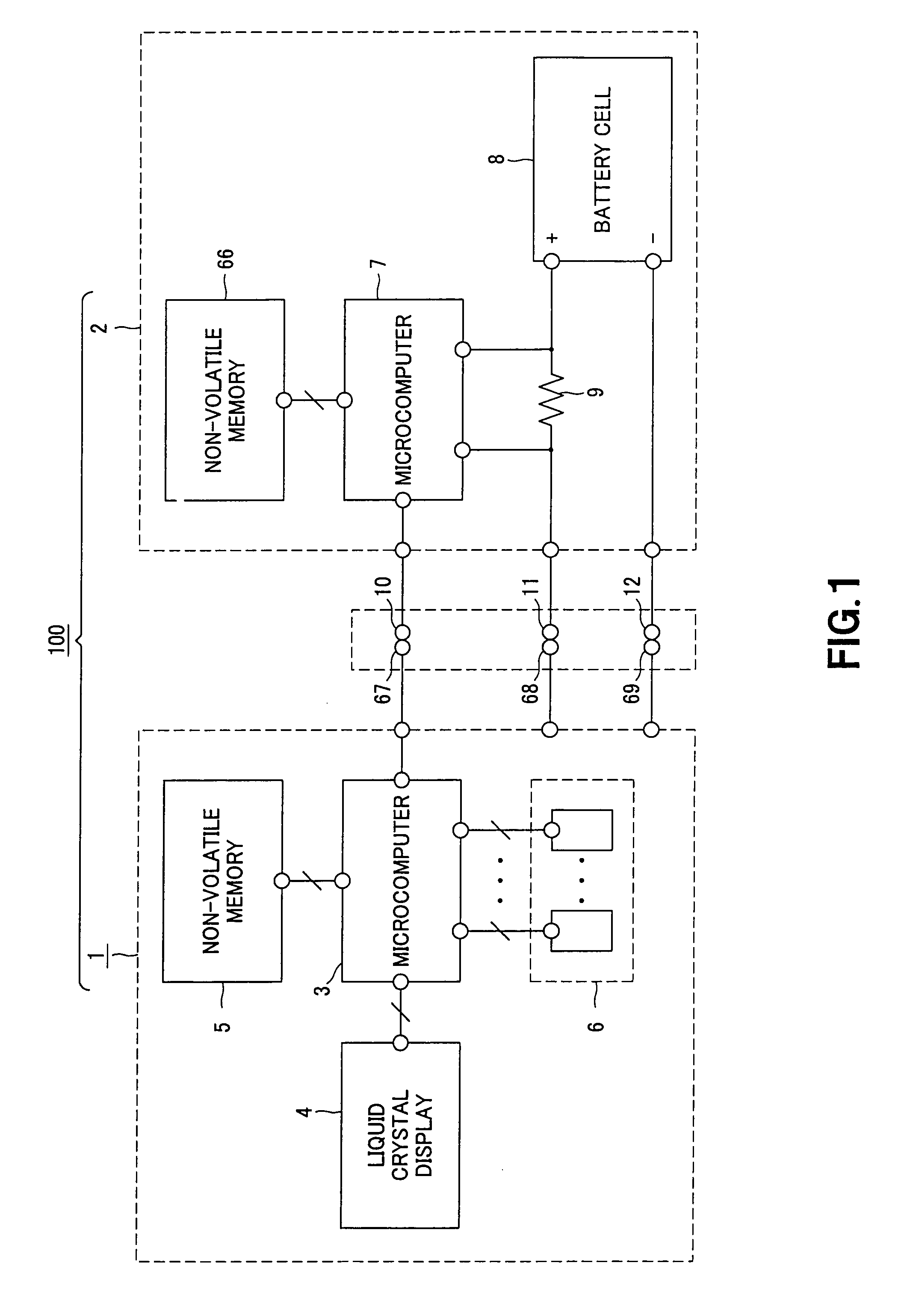
[0025]The present invention is applied to, e.g., a video camera 100 having a configuration as shown in FIG. 1. The video camera 100 is composed of a camera body 1, and a battery pack 2 detachably loaded at the camera body 1 and serving to supply power through connection terminals.

[0026]At the camera body 1, there are provided a first microcomputer 3, a LCD (Liquid Crystal Display) 4, a non-volatile memory 5, and several other devices 6 necessary for constituting the video camera 100.

[0027]The first microcomputer 3 is connected ...


PUM


Abstract

A battery pack detachably connectable to an equipment body to supply power to the equipment body, the battery pack including a battery cell, a microcomputer for communicating with the equipment body, a connection terminal connected to the microcomputer, a positive power supply input terminal connected to a cathode of the battery cell; and a negative power supply input terminal connected to an anode of the battery cell. After the power of the equipment body is turned on, the microcomputer alternately sends to the equipment body by serial communication via the connection terminal information to be used in authentication processing executed by the equipment body and information to be used in a battery residual quantity count executed by the equipment body. After the authentication processing is complete, the microcomputer sends to the equipment body information to be used in updating the battery residual quantity count executed by the equipment body.

Description

CROSS REFERENCE TO RELATED APPLICATIONS[0001]This application is a continuation of U.S. application Ser. No. 10 / 587,256, filed on Jul. 26, 2006, and is based upon and claims the benefit of priority to International Application No. PCT / JP06 / 302946, filed on Feb. 20, 2006 and from the prior Japanese Patent Application Nos. 2005-067818 filed on Mar. 10, 2005. The entire contents of each of these documents are incorporated herein by reference.FIELD OF THE INVENTION[0002]The present invention relates to a battery residual quantity display method in an electronic equipment comprising an equipment body within which a microcomputer having communication function is mounted, and a battery pack detachably loaded at the equipment body and adapted so that a microcomputer having communication function to perform serial communication to and from the microcomputer of the equipment body side is mounted, the battery pack serving to supply power to the equipment body, and an electronic equipment using...

Claims


Application Information

Patent Timeline
Patent Type & Authority Patents(United States)
IPC IPC(8): G08B21/00
CPCG01R31/3682G06F1/3203G06F21/81H04L63/08H01M10/4257H01M10/48H01M10/488H01M10/4221G01R31/3646Y02E60/10G06F1/28H01M50/204G06F1/26
Inventor NAKASHIMA, RYOICHISATO, HIDEYUKITSUCHIYA, YUKIONAWA, KAZUYASU
Owner SONY CORP
Why Eureka
Try Eureka