
Video quality adaptive coding artifact reduction

a technology of adaptive coding and video quality, applied in the field of video post processing, can solve the problems of rarely considering the video quality of the input video, over-smoothing of relatively high quality video, and artifacts may occur, so as to reduce the artifact reduction filter strength, reduce the effect of artifact reduction, and avoid blurring image detail

Inactive Publication Date: 2011-01-04
SAMSUNG ELECTRONICS CO LTD
View PDF17 Cites 26 Cited by
  • Summary
  • Abstract
  • Description
  • Claims
  • Application Information

AI Technical Summary

Benefits of technology

The present invention provides a video quality adaptive coding artifact reduction method and system that employs input video quality analysis to control artifact reduction. The system includes a video quality analyzer, an artifact reducer, and a filter strength controller. The video quality analyzer accesses the video quality of the decoded video sequence and uses it to estimate the input video quality. The estimate is then used to control the strength of the filtering process using the filter strength controller. This results in a more efficient reduction of coding artifacts for low quality input video, while avoiding blurring of image detail for high quality input video. The technical effect of the invention is to improve video quality and reduce the impact of coding artifacts on video quality.

Problems solved by technology

However, using DCT-based compression techniques some artifacts may occur, especially at low and moderate bit rates.
While various coding artifact reduction techniques have shown their effectiveness in different situations, a common shortcoming of such techniques is that they rarely consider the video quality of the input video.
Therefore, such techniques treat the high quality video and the low quality video the same way, which unavoidably leads to over-smoothing of relatively high quality video, and insufficient artifact reduction for relatively low quality video.

Method used


Image

  • Video quality adaptive coding artifact reduction
  • Video quality adaptive coding artifact reduction
  • Video quality adaptive coding artifact reduction

Examples


Embodiment Construction

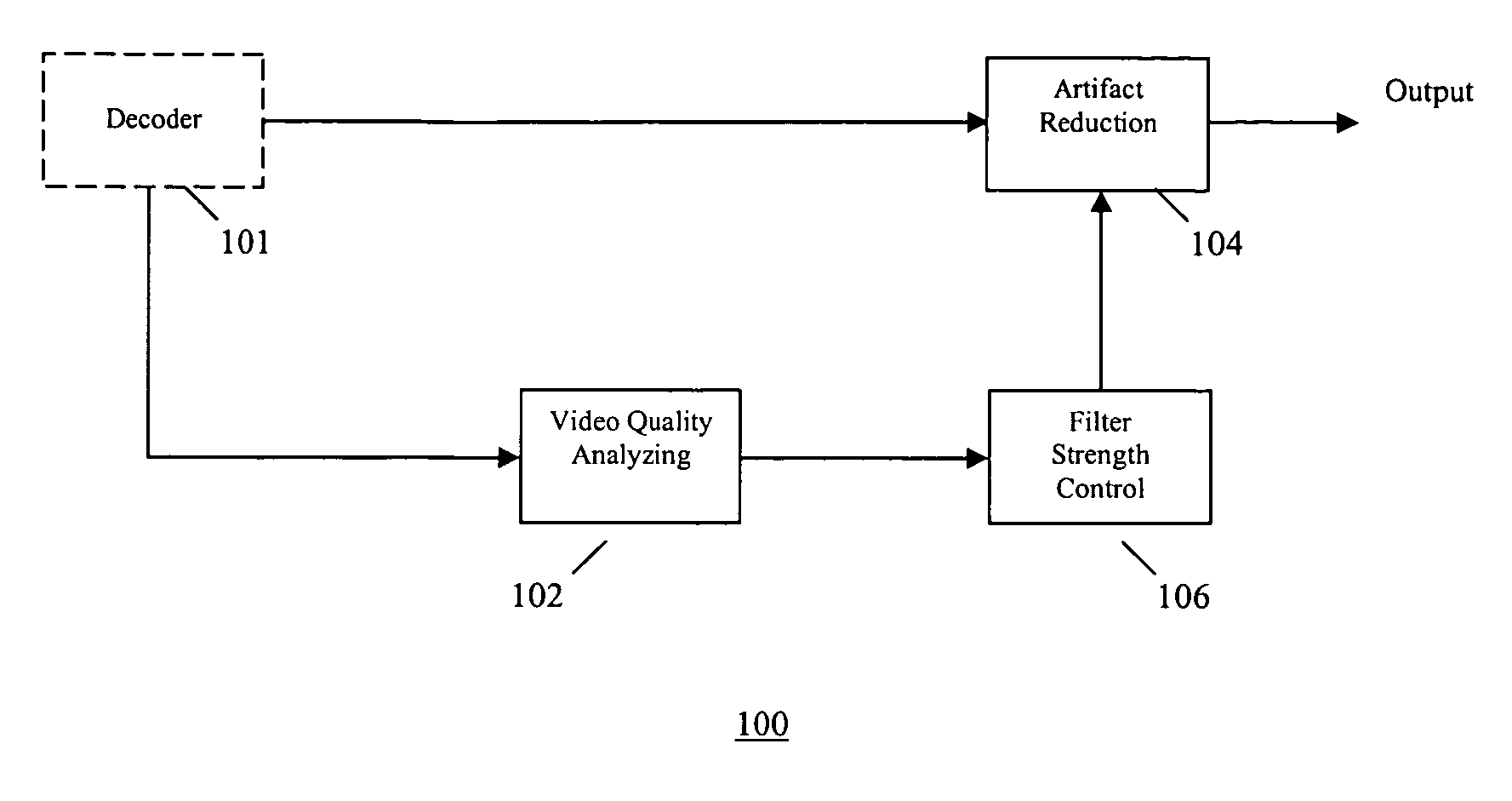
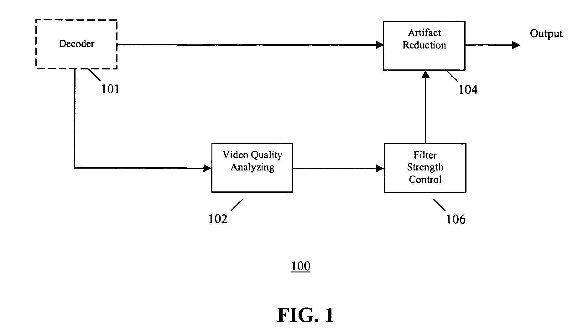
[0013]Referring to the drawings, the present invention provides a video quality adaptive coding artifact reduction method and system that implements input video quality analysis to control artifact reduction. Referring to FIG. 1, according to an embodiment of the present invention, a video quality adaptive coding artifact reduction system 100 includes a video quality analyzer 102, an artifact reducer 104, and a filter strength controller 106. The system 100 can optionally include a decoder 101 for decoding encoded input video sequence.

[0014]The video quality analyzer 102 accesses the video quality of the decoded video sequence. The video quality analyzer 102 can either use the decoded video sequence or other coding parameters, or both, to provide an estimate of the input video quality. In one embodiment, the video quality analyzer 102 first computes the frame average quantizer scale to obtain a frame image quality estimate. Then, the frame image quality estimate is properly weighted...


PUM


Abstract

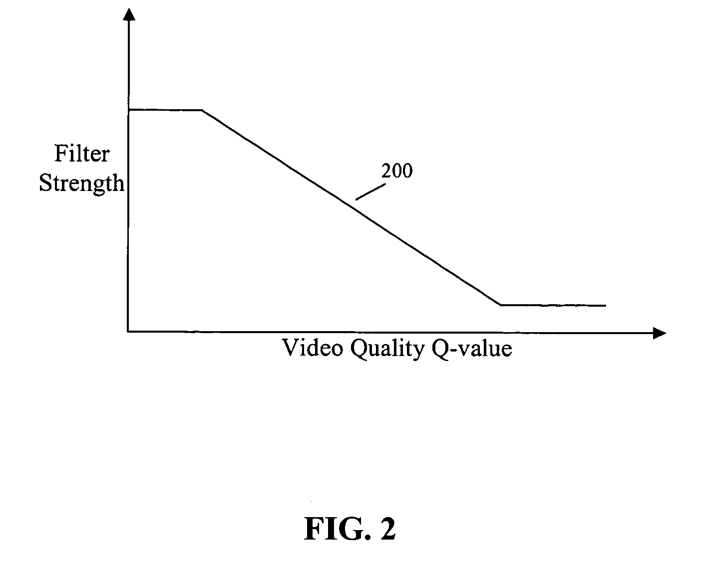
A video quality adaptive coding artifact reduction system has a video quality analyzer, an artifact reducer, and a filter strength controller. The video quality analyzer employs input video quality analysis to control artifact reduction. The video quality analyzer accesses the video quality of the decoded video sequence to estimate the input video quality. The filter strength controller globally controls the filter strength of the artifact reducer based on the video quality estimate by the video quality analyzer. For low quality input video, the filter strength controller increases the artifact reduction filter strength to more efficiently reduce the artifact. For high quality input video, the filter strength controller decreases the artifact reduction filter strength to avoid blurring image detail.

Description

FIELD OF THE INVENTION[0001]The present invention relates generally to video post processing, and more particularly to coding artifact reduction in decoded video sequences.BACKGROUND OF THE INVENTION[0002]Many popular video compression standards, such as MPEG-1, MPEG-2 and H.263, are based on Discrete Cosine Transform (DCT). The basic approach of the DCT-based video compression technique is to subdivide the video image into non-overlapping blocks and then individually transform, quantize, and encode each block. However, using DCT-based compression techniques some artifacts may occur, especially at low and moderate bit rates. Two most noticeable artifacts are mosquito noise (or ringing artifact) and blocking artifact. Mosquito noise mostly appears in image homogeneous regions near strong edges. It is caused by loss of high frequency transform coefficients during quantization. Blocking artifacts appear as artificial discontinuities between the boundaries of the blocks. It is caused by...

Claims


Application Information

Patent Timeline
Patent Type & Authority Patents(United States)
IPC IPC(8): G06K9/40H04N11/04G06K9/00H04N7/12H04N11/02
CPCH04N19/159H04N19/172H04N19/61H04N19/86H04N19/14H04N19/154H04N19/117E06B9/38E06B9/322E06B2009/587
Inventor LIN, PENGKIM, YEONG-TAEG
Owner SAMSUNG ELECTRONICS CO LTD
Learn More