Deflecting a beam of electrically charged particles onto a curved particle path

a technology of electrically charged particles and curved particles, which is applied in the direction of magnetic bodies, instruments, and treatment, etc., can solve the problems of inability to meet the requirements of ion-optic parallelism and at the same time homogeneous spatial distribution of particles in the plane, and the deflection angle is not acceptable in terms of weight and cost, and achieves maximum beam guidance. the effect of precis

Active Publication Date: 2011-01-11
VARIAN MEDICAL SYST PARTICLE THERAPY GMBH & CO KG
View PDF9 Cites 48 Cited by
  • Summary
  • Abstract
  • Description
  • Claims
  • Application Information

AI Technical Summary

Benefits of technology

[0012]The present embodiments may obviate one or more of the drawbacks or limitations inherent in the related art. For example, in one embodiment, a device deflects a beam of electrically charged particles onto a curved particle path. The device allows maximally precise beam guidance in a simple manner also in the case of a scanned particle beam.

Problems solved by technology

When ferromagnetic yoke material is used, the necessary deflection angle is only achieved with a size of magnet system that is unacceptable in terms of weight and costs.
When a deflection magnet is being configured, a problem that routinely occurs is that the ion-optic requirements in terms of parallelism with at the same time homogeneous spatial distribution of the particles in the plane of the isocenter (for linearly driven scanner magnets) cannot be perfectly fulfilled in principle. FIG. 3 shows an example of a spatial and angular deviation for a coil configuration.
When ferromagnetic components are used, for example, for shielding individual components, the B fields are no longer linear to the current, as a result of which the imaging can only be optimal for one ion energy.
The possibilities of fulfilling the ion-optic requirements (parallelism and desired spatial distribution) are essentially limited.
Limitations arise, for example, from the limited current carrying capacity of real conductors.
Arbitrarily high requirements in terms of parallelism with simultaneous homogeneous spatial distribution can only be achieved with very great deflection radii.
This, however, conflicts with the requirement for wanting to implement as compact and lightweight a deflection magnet as possible.

Method used


Image

  • Deflecting a beam of electrically charged particles onto a curved particle path
  • Deflecting a beam of electrically charged particles onto a curved particle path
  • Deflecting a beam of electrically charged particles onto a curved particle path

Examples


Embodiment Construction

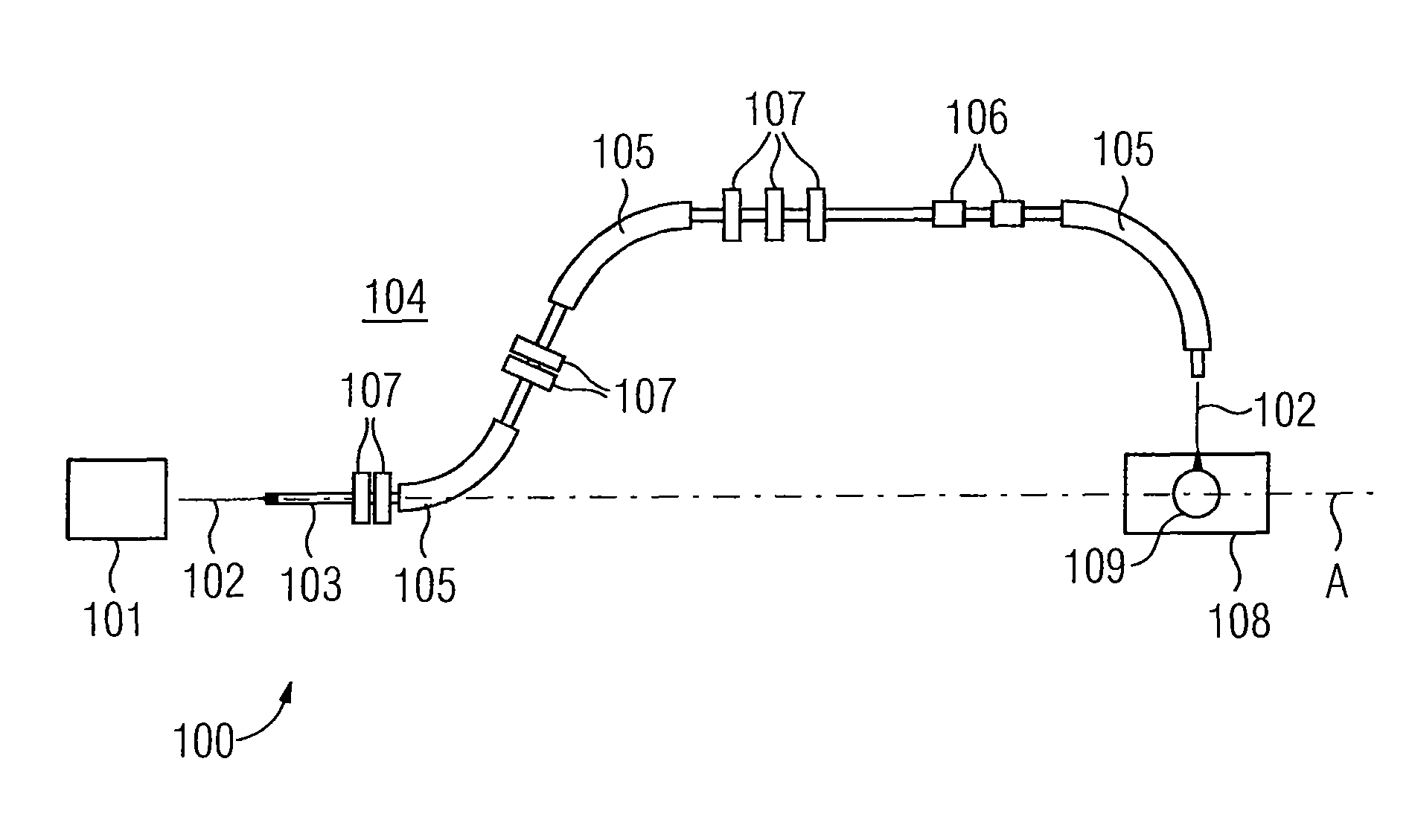
[0025]FIG. 1 shows an irradiation facility 100 by which a beam of electrically charged particles (particle beam) 102 emerging from a particle source or accelerator 101 is deflected along a curved particle path with a gantry system. The particle beam 102 may be a beam of C6+ ions. The particle beam 102 is guided inside a beam guidance tube 103. A beam guidance plane 104 is the curved path of the particle beam 102. The particle beam 102 is deflected (or, as the case may be, focused) several times from a direction predefined by the particle source or accelerator 101 from the particle beam's 102 original direction by a plurality of deflection magnets 105 and / or quadrupole magnets 107. Deflection magnets 105 and / or quadrupole magnets 107 and further magnets, for example, scanner magnets 106, are part of the gantry system which is rotatable around a specified rotation axis A. In addition to the deflection magnets 105, quadrupole magnets 107 and scanner magnets 106, a gantry system include...


PUM

PropertyMeasurementUnit
magnetic flux densityaaaaaaaaaa
electric field strengthaaaaaaaaaa
voltageaaaaaaaaaa

Abstract

A device for deflecting a beam of electrically charged particles onto a curved particle path is provided. The device includes at least one beam guidance magnet having a coil system which has at least one coil that is curved along the particle path for the purpose of deflecting the beam onto a curved particle path, and at least one scanner magnet for variably deflecting the beam in a y,z plane at right angles to the particle path, characterized in that the device has at least one correction system which is embodied to influence the particle path in a regulated or controlled manner with the aid of electric and / or magnetic fields as a function of the position of the beam in the y,z plane. The invention also relates to a corresponding method for deflecting a beam of electrically charged particles onto a curved particle path.

Description

[0001]This patent document claims the benefit of German patent application DE 10 2007 050 035.3, filed Oct. 17, 2007, which is hereby incorporated by reference.BACKGROUND[0002]The present embodiments relate to deflecting a beam of electrically charged particles onto a curved particle path.[0003]Particle therapy includes accelerating ions of hydrogen (protons), carbon (C12) or other elements to high velocities (equivalent to energies of 50-500 MeV / nucleon) and directing the ions or other elements onto tumor tissue that is to be treated. The depth of penetration into the tissue can be set by varying the particle energy. The ions are generated and accelerated in a part of the system, which because of the part's size, that is stationary. The part of the system is immovable. The tumor may be irradiated from different directions. Accordingly, a movable magnet system for guiding and deflecting the ion beam may be provided. The magnet system may be adjustable in strength in order to enable ...

Claims


Application Information

Patent Timeline
Patent Type & Authority Patents(United States)
IPC IPC(8): G01K1/08H01J3/14H01J3/26
CPCA61N5/1043G21K1/087G21K1/093H05H7/04A61N2005/1087
Inventor DIEHL, DIRK
Owner VARIAN MEDICAL SYST PARTICLE THERAPY GMBH & CO KG
Why Eureka
Try Eureka