Flexible pixel element fabrication and sealing method

a flexible, pixel element technology, applied in the direction of identification means, electrical apparatus casings/cabinets/drawers, instruments, etc., can solve the problems of more advanced light emitting elements or pixels, such as leds and lcds, that are more expensive to use and replace, and need to protect delicate and vulnerable internal electronic components from failure, etc., to achieve better withstand, improve the longevity of pixel element electronics, and improve the effect of adapted to application

Active Publication Date: 2011-01-11
DAKTRONICS
View PDF16 Cites 69 Cited by
  • Summary
  • Abstract
  • Description
  • Claims
  • Application Information

AI Technical Summary

Benefits of technology

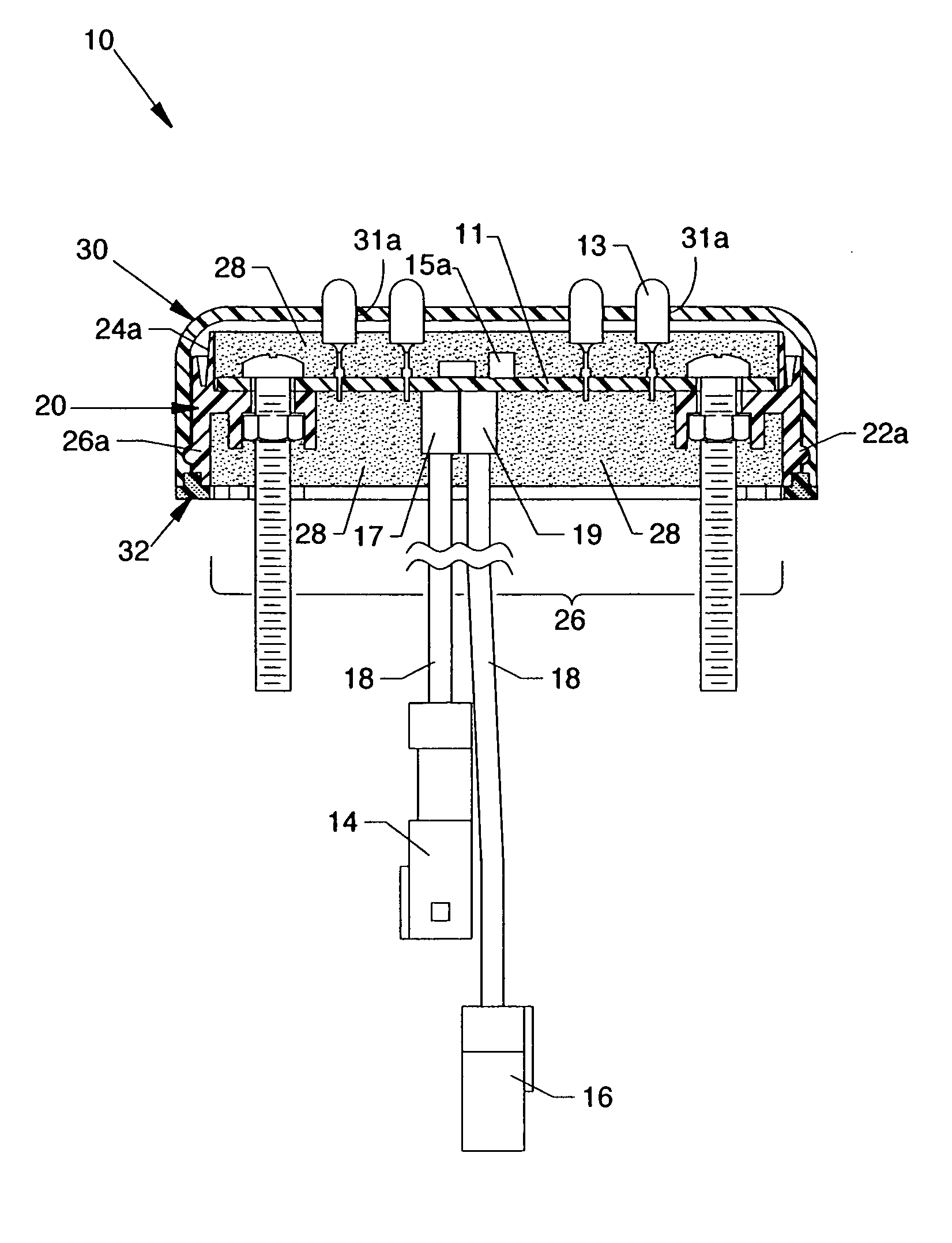
[0017]The general purpose of the present invention is to protect delicate and vulnerable pixel element electronics used in discrete flexible pixel elements from failure and damage due to detrimental effects of environment. More specifically, the present invention discloses a fabrication method and means for hermetic sealing of pixel element electronics embodied within discrete flexible pixel elements. The fabrication method comprises an encapsulation means and an external casement means. In addition, the fabrication method embodies connection means for connecting power and signal cables conjoining a plurality of discrete flexible pixel elements in series-connection, wherein electrical conductors and terminal contacts embodied within said power and signal cables are similarly protected.

Problems solved by technology

An inherent problem in the design and manufacture of large scale electronic display devices for outdoor use is the need to protect delicate and vulnerable internal electronic components from failure due to the detrimental effects of environment.
This problem is exacerbated by the increasing sophistication of light emitting elements and their collateral support electronics, such as the electronic drivers for the light emitting elements.
More advanced light emitting elements or pixels, such as LEDs and LCDs, are more expensive to use and replace.
In addition, they require more numerous and more expensive collateral support electronics, including pixel element drivers, data buffers, control signal handlers, over-voltage and transient protection circuits, to name a few.
Furthermore, advanced light emitting elements and collateral support electronics are comparatively much more delicate and easily damaged by electrostatic shock, thermal shock, mechanical shock, moisture and humidity, and various other detrimental environmental conditions.
Advanced light emitting elements and collateral support electronics also require more sophisticated means of mounting and electrical connection, such as surface mounted printed circuit boards (PCBs), as well as more sophisticated means of supplying operating power, digital image data and display control signals, which means greatly increase the number of signal paths and conductors needed to service components and thereby greatly increase the number of connection points and potential points of failure.
Therefore, the use of advanced light emitting elements, while presenting advantages in terms of the sophistication of visual output images that can be displayed, also presents a vulnerable design architecture with many potential points of failure.
Not only does this add to the cost of producing already expensive large scale outdoor electronic displays and signage, but such enclosures are generally effective only for conventional, rectilinear or planar displays mounted on flat surfaces.
Producing collective enclosures that conform to irregular shaped surfaces can be a complex and costly undertaking.
Moreover, a collective enclosure typically embodies a single-point failure mode, wherein any failure of the collective enclosure exposes all the light emitting elements, collateral support electronics and connection points contained therein to potential failure.
Finally, collective enclosures are subject to overheating from both internal and external sources, including component power dissipation and solar radiation.
Conventional collective enclosures are not well suited for protecting electronic display devices that conform to irregular shapes and surfaces since they are difficult and expensive to fabricate.
Furthermore, they embody a single point failure mode which exposes all internal components and connections to potential failure, as well as being subject to overheating.
As a result, production of such enclosures is cost prohibitive, while outcomes are often inelegant and failure prone.

Method used


Image

  • Flexible pixel element fabrication and sealing method
  • Flexible pixel element fabrication and sealing method
  • Flexible pixel element fabrication and sealing method

Examples


Embodiment Construction

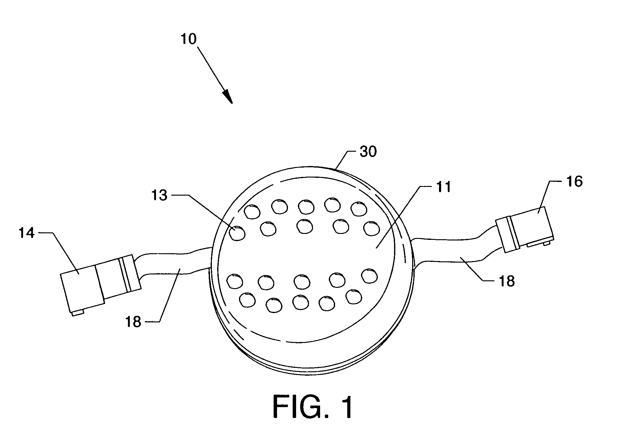
[0046]FIG. 1 is an isometric view of a preferred embodiment of discrete flexible pixel element 10 of the present invention. The flexible pixel element 10 embodies a printed circuit board assembly (not shown) on which various surface mounted electrical components are soldered or mechanically fastened to conductor pads by operative electrical connection including a plurality of light emitting elements 13, top encasement cover 30, input connector 14, output connector 16, and flexible cables 18 embodying in assembly a unitary, self-contained, replaceable module. The light emitting elements 13, or pixels, are illuminated when energized by on-board pixel element drivers (not shown) to produce a visual output in the form of emitted light. In a preferred embodiment, the light emitting elements 13 comprise a plurality of red, green and blue (RGB) colored LEDs.

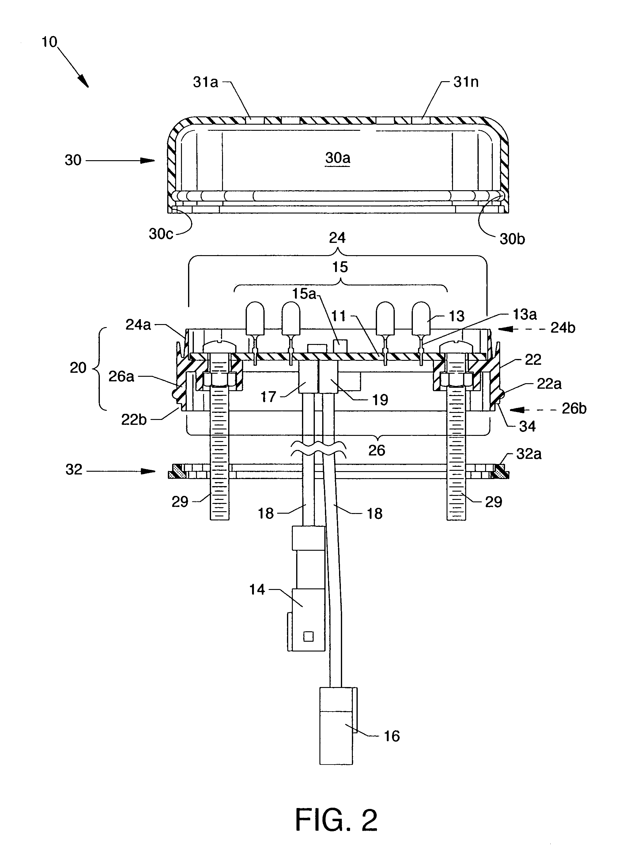
[0047]FIG. 2 is a cross section side view of potting assembly 20, a top encasement cover 30, and a bottom gasket 32. Printed circuit b...


PUM

PropertyMeasurementUnit
heightaaaaaaaaaa
shapeaaaaaaaaaa
Flexibleaaaaaaaaaa

Abstract

Discrete flexible pixel elements are hermetically sealed from the environment and comprise unitary, self-contained replaceable modules which enable efficient, economical production of large scale, free-form electronic displays, signs and lighting effects for outdoor use. The method and means for producing hermetically sealed discrete flexible pixel elements include encapsulation means, exterior casement means, and cable connector means.

Description

CROSS REFERENCES TO RELATED APPLICATIONS[0001]This application is a continuation-in-part of application Ser. No. 10 / 965,133 filed on Oct. 14, 2004, entitled “Flexible Pixel String Hardware and Method”, which is pending.[0002]This application claims priority from the earlier filed U.S. Provisional Application No. 60 / 926,706 filed Apr. 27, 2007, entitled “Flexible Pixel Assemblies for Mounting on Irregular Surfaces”, and is hereby incorporated into this application by reference as if fully set forth herein.[0003]This application is related to patent application Ser. No. 10 / 965,127 filed on Oct. 14, 2004, entitled “Flexible Pixel String Software and Method”, which is pending.[0004]This application is also related to U.S. utility patent application entitled “Flexible Pixel Element and Signal Distribution Means”, application number to be assigned, filed concurrently herewith, a copy of which is attached and the disclosure of which is incorporated by reference as if fully set forth herein...

Claims


Application Information

Patent Timeline
Patent Type & Authority Patents(United States)
IPC IPC(8): G09G5/04
CPCG09F9/33G09F13/22H05K5/064G09G3/06G09F9/301F21V15/01G09G3/32G09G2310/0221H05K3/284Y10T29/49126G09G3/12G09G2300/04G09G2300/0426F21Y2115/10Y10T29/49128F21V31/005F21V23/06H05K3/368H05K3/32
Inventor WENDLER, BRETT D.BRAVEK, ERIC S.GREBEL, ERICH J.
Owner DAKTRONICS
Why Eureka
Try Eureka