
Method and system for data collection and analysis

a data collection and analysis technology, applied in the field of methods and systems for collecting and analyzing data from relatively complex equipment, can solve the problems of locomotives experiencing failures while in service, power generation, and other problems, and achieve the effect of avoiding failures, avoiding failures, and avoiding failures

Active Publication Date: 2011-01-11
GE GLOBAL SOURCING LLC
View PDF32 Cites 61 Cited by
  • Summary
  • Abstract
  • Description
  • Claims
  • Application Information

AI Technical Summary

Benefits of technology

Significantly reduces labor costs and improves efficiency by allowing one technician to perform maintenance on multiple locomotives in a fraction of the time, enhancing the accuracy and reliability of testing, diagnostic, and predictive maintenance.

Problems solved by technology

The testing, diagnosis, repair, maintenance and / or other servicing of generally complex equipment, such as mobile assets that may include on-road or off-road vehicles, ships, airplanes, railroad locomotives, trucks, and other forms of complex equipment including industrial equipment, consumer appliance equipment, medical imaging equipment, equipment used in industrial processes, telecommunications, aerospace applications, power generation, etc., often involves complex and time consuming processes.
Locomotives may also experience failures while in service and undergo daily inspections.
The scope and quantity of these services adds a significant cost to an operators' expenses, especially to those having hundreds or more locomotives in service.
This process is labor intensive and error prone, which increases operators' costs and may lead to incorrect testing and diagnosis.
This approach for data collection and analysis is slow, limits the type and quantity of data retrieved and analyzed, and limits the extent to which the data may be analyzed for testing, diagnostic and predictive maintenance.
This process is labor intensive and time consuming, and it may typically take two trained technicians about four hours to perform certain maintenance services on one locomotive.

Method used


Image

  • Method and system for data collection and analysis
  • Method and system for data collection and analysis
  • Method and system for data collection and analysis

Examples


Embodiment Construction

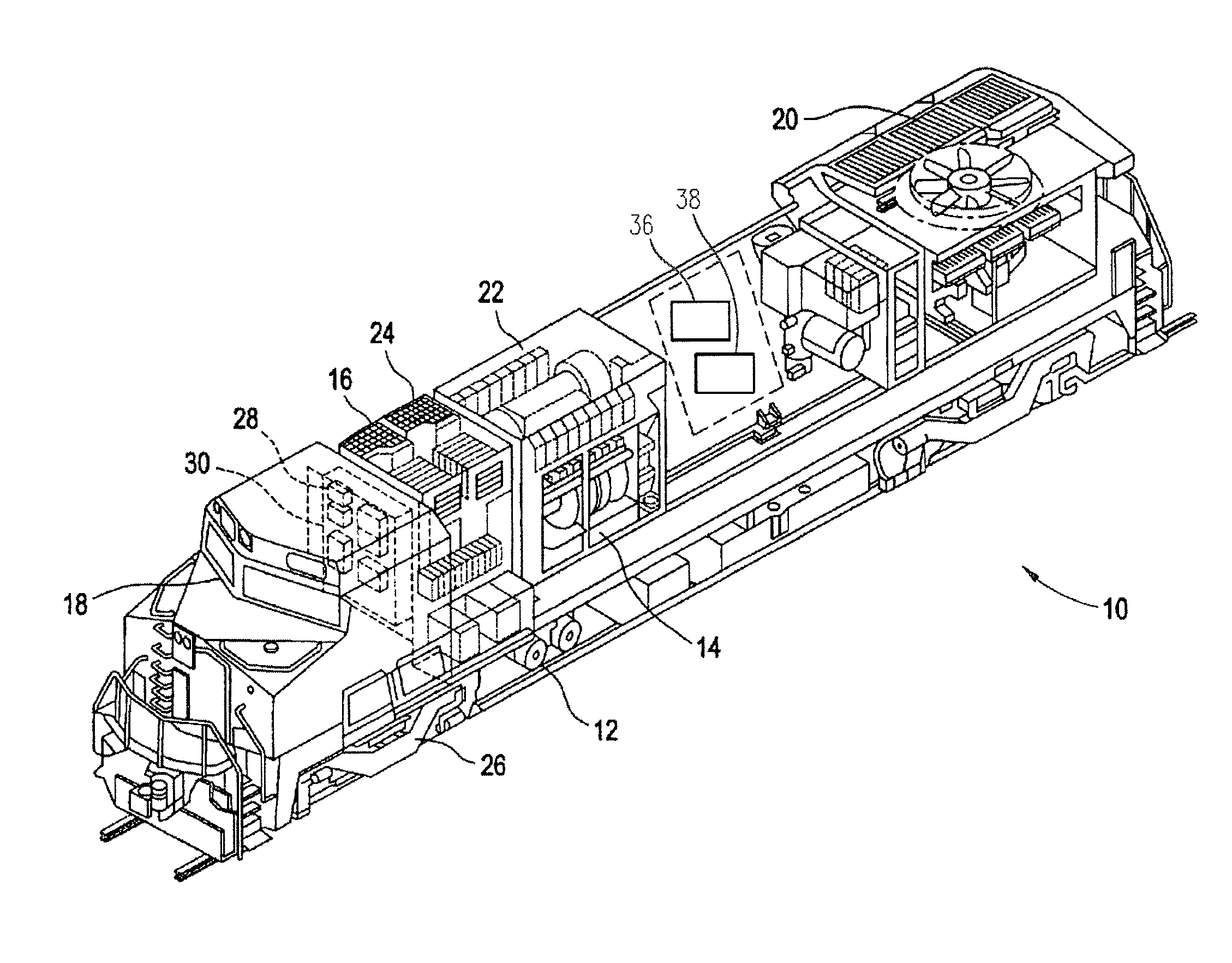
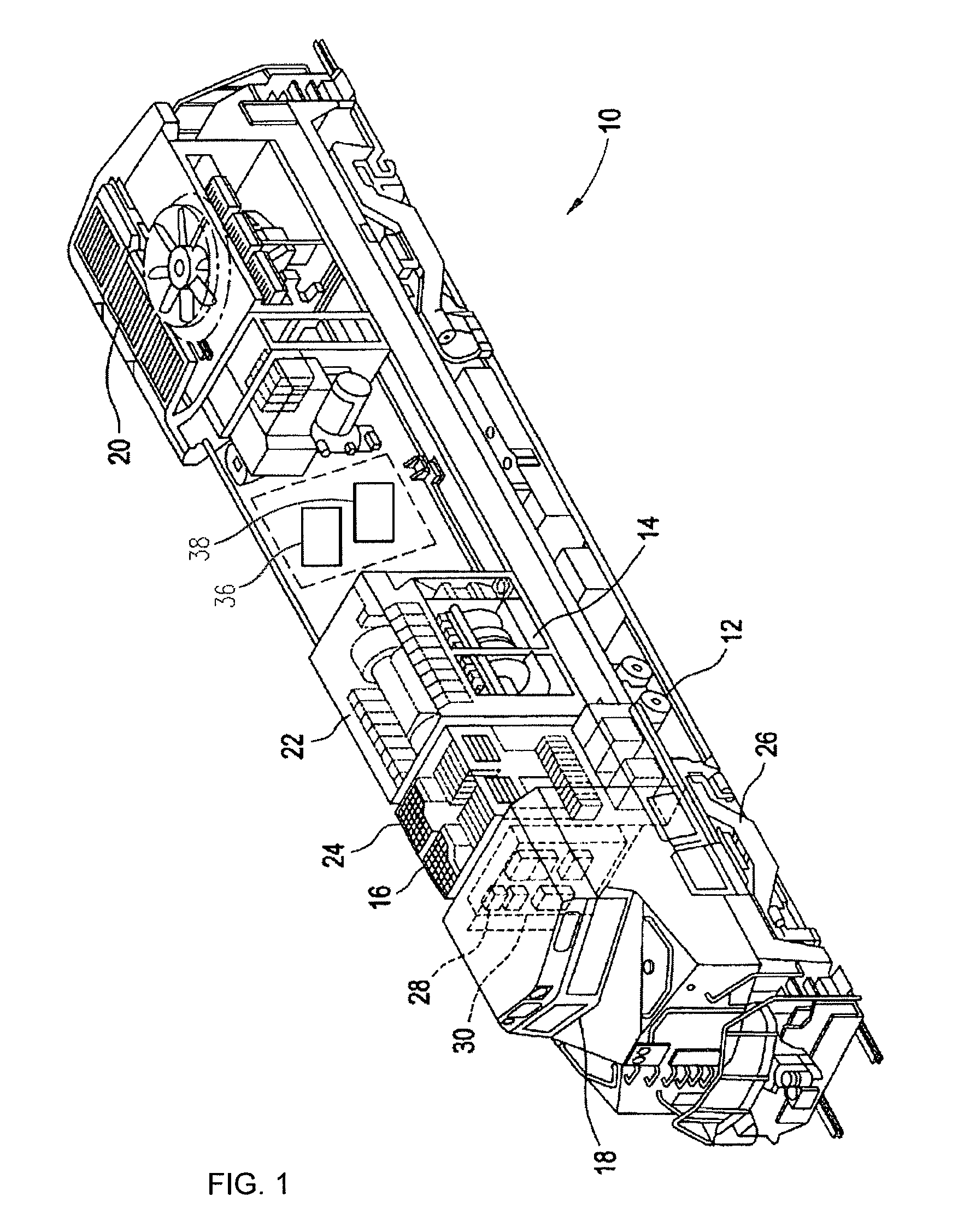
[0016]FIG. 1 illustrates a schematic of a locomotive 10 having exemplary on-board systems and subsystems. Locomotive 10 may include a plurality of such systems and subsystems such as, for example, an air and air brake subsystem 12, an auxiliary alternator subsystem 14, a battery and cranker subsystem 16, a cab signal subsystem 18, an engine cooling subsystem 20, an equipment ventilation subsystem 22, a propulsion subsystem 24, a traction alternator subsystem 26, a locomotive control system 28 and an on-board diagnostics subsystem 30. It will be appreciated that locomotive 10 may comprise a wide range of systems and subsystems and that the present invention is not limited to specific systems or subsystems disclosed herein.

[0017]One or more systems and / or subsystems on-board locomotive 10 may be associated with one or more on-board computers, also referred to herein as “panels”, such as panels 36, 38. Panels 36, 38 may be microprocessor controlled and have respective databases associa...


PUM


Abstract

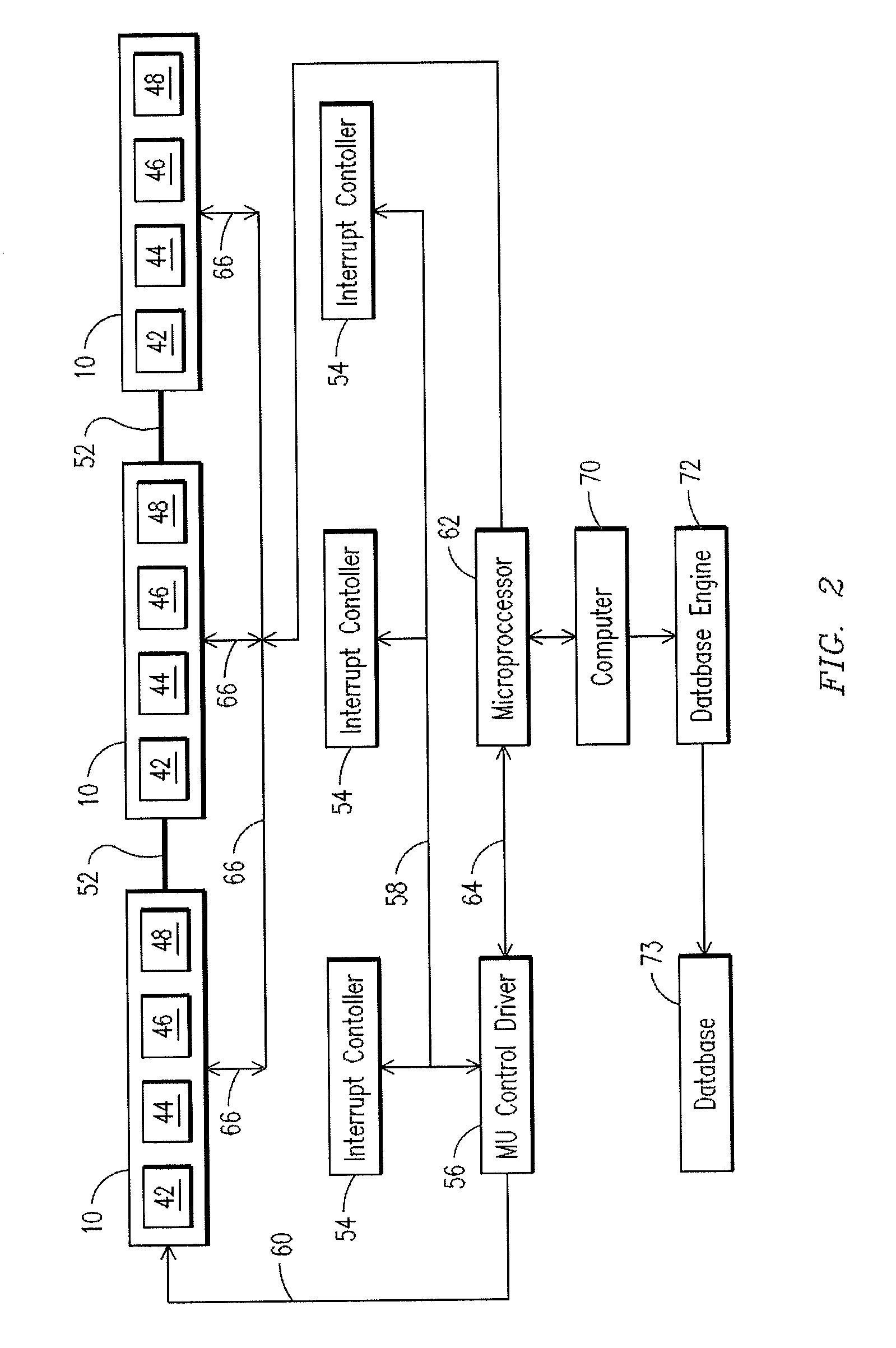
A computer-implemented system and method of contemporaneously testing a respective system on-board each of a plurality of locomotives with a common user interface where the locomotives are in electrical communication with one another for transmitting electronic signals among the locomotives. An electronic signal may be transmitted to the plurality of locomotives instructing a respective on-board computer of each locomotive to synchronously engage a self-load sequence. An electronic signal may be transmitted to the plurality of locomotives instructing a respective engine of each locomotive to execute a testing sequence. Operating parameter data associated with the respective systems may be downloaded from each of the plurality of locomotives through the common user interface to a database engine to determine whether the downloaded operating parameter data is within acceptable operating limits.

Description

BACKGROUND OF THE INVENTION[0001]This invention relates generally to a method and system for collecting and analyzing data from relatively complex equipment, and, more particularly, to a computer-based method and system for acquiring data simultaneously from one or more locomotives for testing, diagnostic and predictive maintenance.[0002]The testing, diagnosis, repair, maintenance and / or other servicing of generally complex equipment, such as mobile assets that may include on-road or off-road vehicles, ships, airplanes, railroad locomotives, trucks, and other forms of complex equipment including industrial equipment, consumer appliance equipment, medical imaging equipment, equipment used in industrial processes, telecommunications, aerospace applications, power generation, etc., often involves complex and time consuming processes.[0003]With respect to transportation equipment such as locomotives, the efficient and cost-effective operation of a locomotive or fleet of locomotives dema...

Claims


Application Information

Patent Timeline
Patent Type & Authority Patents(United States)
IPC IPC(8): G06F17/00G01C22/00G06G7/70G06F11/00
CPCB61L15/0081G06F11/2294
Inventor WALKER, JOHN DAVID
Owner GE GLOBAL SOURCING LLC
Learn More