Method of manufacturing a spherical bearing

a technology of spherical bearings and bearings, which is applied in the direction of pivotal connections, rotary machine parts, mechanical equipment, etc., can solve the problems of affecting the rotation of the ball portion the ball portion is in excessive contact with the resin liner, and the ball portion is difficult to freely rotate relative to the resin liner

Active Publication Date: 2011-01-18
THK CO LTD
View PDF24 Cites 8 Cited by
  • Summary
  • Abstract
  • Description
  • Claims
  • Application Information

AI Technical Summary

Benefits of technology

[0010]The present invention has been made in view of the above problem. It is an object of the present invention to provide a spherical bearing manufacturing method which allows in a simple manner smooth rotation of the ball portion relative to the outside member after the casting and which makes it possible to completely eliminate the gap between the ball portion and the resin liner, making it possible to maintain a satisfactory slide contact between the ball portion and the resin liner for a long period of time.
[0011]To achieve the above object, the present invention provides a spherical bearing manufacturing method in which a metal ball portion constituting the inside member is inserted into a mold as a core before performing injection molding to form a resin liner covering the ball portion. This resin liner is molded by using the ball portion as the core, so that no gap exists between the resin liner and the spherical surface of the ball portion, and the spherical surface of the ball portion is transferred as it is to the resin liner. Thus, by using a bearing steel ball of high sphericity as the ball portion, it is possible to form a satisfactory mirror-surface-like slide surface on the resin liner, making it possible to bring this slide surface into close contact with the ball portion. Further, by molding the resin liner so as to cover the equator of the ball portion, it is possible to prevent the resin liner after molding from being separated from the ball portion. Accordingly it is possible to hand the ball portion and the resin liner as an integral unit in the subsequent manufacturing processes.
[0012]Next, the ball portion with the resin liner attached thereto is inserted into the mold as a core, and the outside member covering the resin liner from outside is cast. From the viewpoint of enhancing the dimensional accuracy of the spherical bearing manufactured, the casting is preferably squeeze casting; further, from the viewpoint of mass production, die-casting, which allows setting of the cycle time short, is preferable. Examples of the alloy that can be used for casting include zinc alloy, aluminum alloy, magnesium alloy, and titanium alloy; in the case of a spherical bearing used in a leg part such as an automotive suspension structure, it is desirable to use an aluminum alloy, magnesium alloy, etc. from the viewpoint of a reduction in weight.
[0014]Thus, in the method of the present invention, after the casting of the outside member, the resin liner covering the ball portion is heated through the ball portion of the inside member. The resin liner encloses and is in close contact with the ball portion, so that, when the ball portion is heated, the heat energy is conducted to the resin liner, and the resin liner is also heated to some degree. When, at this time, the resin liner undergoes temperature rise, and is heated to a temperature near the glass transition temperature Tg, the mechanical strength of the resin liner, such as the bending modulus, is gradually reduced, so that the resin liner becomes easily deformable in conformity with the size of the ball portion; when the resin liner is cooled after this heating, the tightening force of the resin liner with respect to the ball portion is reduced. Further, since the heated ball portion expands, it also occurs that the ball portion expands the resin liner, which also contributes to the tendency of the tightening force of the resin liner to be reduced after the cooling of the ball portion.
[0015]Accordingly, by thus heating the resin liner through the ball portion after the casting of the outside member, it is possible to mitigate the force with which the resin liner tightens the ball portion, enabling the ball portion to smoothly rotate relative to the resin liner. Thus, in this method, the ball portion becomes rotatable relative to the resin liner. However, since no gap is formed between the two, it is possible to completely eliminate rattling of the ball portion with respect to the outside member, thus making it possible to effect transmission of load and transmission of motion with high accuracy between the outside member and the inside member even in the case of a long-term use. Further, since it is possible to realize smooth rotation of the ball portion solely by heating the ball portion after the casting of the outside member, the method can be executed very easily, making it possible to easily cope with automation of each manufacturing process and mass production.
[0016]While, in heating the resin liner through the ball portion in the final process, it is only necessary to heat the ball portion, it is also possible to apply an external force to the ball portion, crushing the ball portion within an elastic deformation range. By thus pressurizing the ball portion simultaneously with the heating of the resin liner and crushing the ball portion, the elastically deformed ball acts so as to pressurize the resin liner toward the outside member, so that the effect of expanding the resin liner is enhanced, making it possible to more effectively reduce the force with which the ball portion is tightened by the resin liner.

Problems solved by technology

After the outside member is thus cast, the resin liner tightens the ball portion, and it is difficult for the ball portion to freely rotate relative to the resin liner.
That is, since the resin liner is attached to the ball portion by injection molding using the ball portion as a core, the resin liner tightens the ball portion due to contraction occurring after the injection molding; further, since the outside member also undergoes casting contraction after the casting, the outside member tightens the resin liner toward the ball portion, with the result that the ball portion is excessively in press contact with the resin liner.
Thus, after the casting of the outside member, rotation of the ball portion relative to the resin liner is hindered.

Method used


Image

  • Method of manufacturing a spherical bearing
  • Method of manufacturing a spherical bearing
  • Method of manufacturing a spherical bearing

Examples


first embodiment

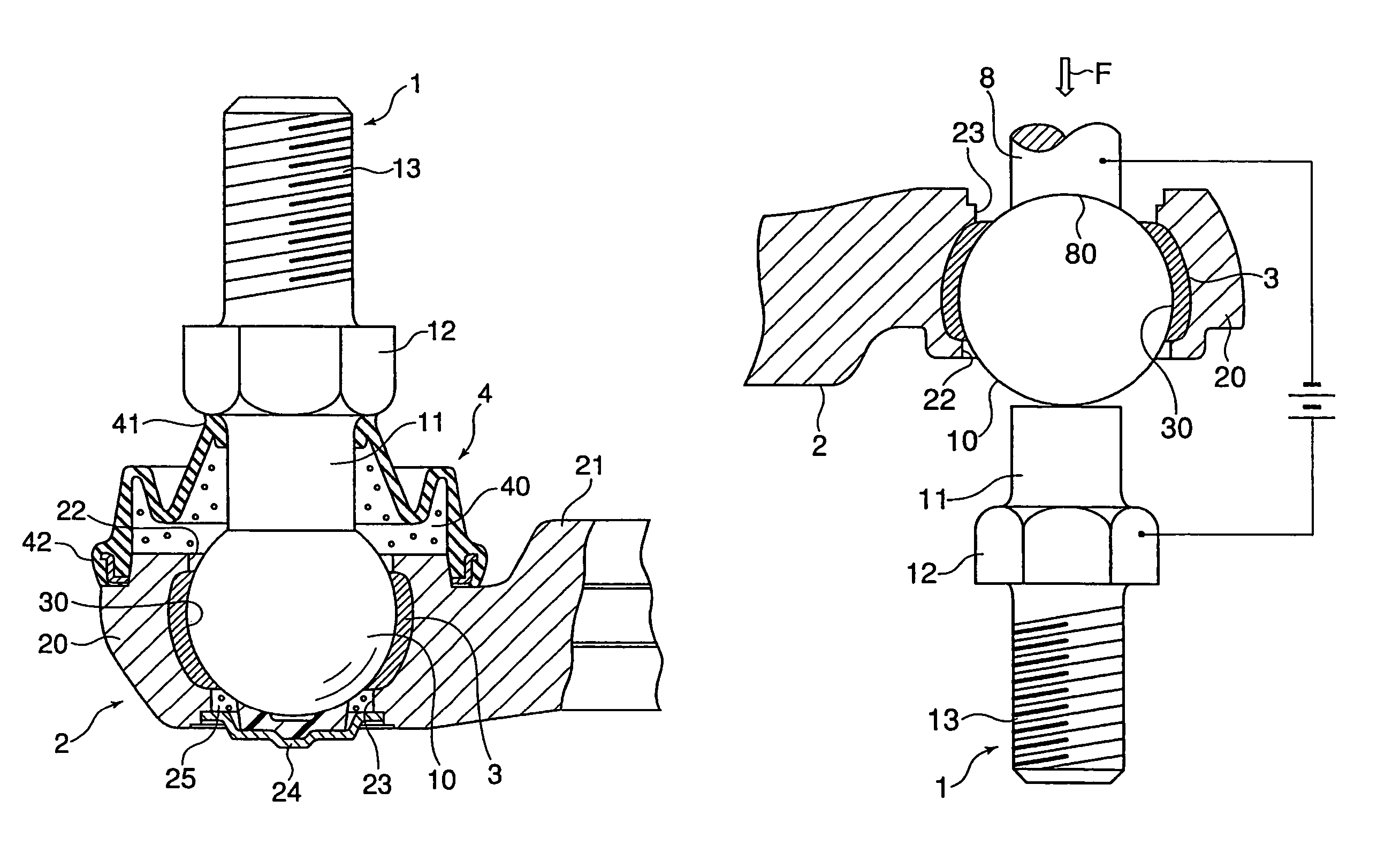
[0032]FIG. 1 shows a spherical bearing to which the present invention is applied. This spherical bearing is composed of a ball shank 1 constituting an inside member with a ball portion at the distal end thereof, and a holder 2 constituting an outside member having a ball support portion 20 enclosing a ball portion 10 of the ball shank 1, with the ball shank 1 and the holder 2 being connected to each other swingably or rotatably.

[0033]The ball shank 1 is formed by welding a bar-like shank 11 to a bearing steel ball of high sphericity constituting the ball portion 10, and at the bottom of the shank 11, there is formed a hexagonal bearing surface 12 for securing a member to be mounted such as a link. Further, a male screw 13 is formed on the distal end portion of the shank 11, and by threadedly engaging a nut with this male screw 13, the member to be mounted can be held and secured between the nut and the hexagonal bearing surface 12.

[0034]On the other hand, the holder 2 is equipped w...

second embodiment

[0053]Next, FIG. 8 is a sectional view of aspherical bearing according the second embodiment manufactured by the method of the present invention.

[0054]This spherical bearing is composed of an outer ring 101 constituting the outside member, an inner ring 102 constituting the inside member, and a resin liner 103 provided between the inner ring 102 and the outer ring 101, in which the inner ring 102 can freely make a swinging movement or a rotating movement relative to the resin liner 103 held by the outer ring 101. The inner ring 102 is formed in an annular configuration with a through-hole 105 into which a rod 104 of a link mechanism is to be inserted, with its outer peripheral surface 106 being finished as a convex spherical surface in slide contact with the resin liner 103. As the material of the resin liner, the same polyether ether ketone as used in the first embodiment was used, and the thickness thereof was 1.0 mm.

[0055]The manufacturing method for the spherical bearing of the ...


PUM

PropertyMeasurementUnit
thicknessaaaaaaaaaa
sphericityaaaaaaaaaa
thicknessaaaaaaaaaa

Abstract

Provided is a method of manufacturing a spherical bearing having an inside member with a metal ball portion and an outside member having a ball support portion enclosing and supporting the ball portion of the inside member and connected to the inside member swingably or rotatably relative to each other, including the steps of performing injection molding in which the ball portion of the inside member is inserted as a core in a mold to mold a resin liner covering the ball portion, molding the outside member covering the resin liner by a casting in which the ball portion and the resin liner are inserted as a core in the mold, and after the completion of the casting, heating the resin liner covering the ball portion through the ball portion of the inside member.

Description

TECHNICAL FIELD[0001]The present invention relates to a spherical bearing in which an inside member having a ball portion serving as a center of the swing of a link mechanism and an outside member enclosing and holding the same are swingably or rotatably coupled to each other, and which is primarily used for a link motion mechanism or the like in a suspension arm part and a steering part of an automobile, a blade driving part of a combine, or the like.BACKGROUND ART[0002]In general, known spherical bearings of this type include bearings which are equipped with an inside member having a ball portion and an outside member enclosing and holding the ball portion of the inside member to be coupled to the inside member such that it can swing or rotate relative to the inside member. The outside member must undetachably enclose and hold the ball portion against any load acting on the inside member. Therefore, with such a spherical bearing, there remains a problem of what kind of structure t...

Claims


Application Information

Patent Timeline
Patent Type & Authority Patents(United States)
IPC IPC(8): B21K1/04B22D15/02B22D17/00F16C11/06
CPCF16C11/0633Y10T29/49657Y10T29/49659Y10T29/49655Y10T29/49648Y10T29/49705F16C11/0642F16C11/0657F16C11/0685F16C2300/02F16C11/06
Inventor MICHIOKA, HIDEKAZUMURATA, TOMOZUMINISHIDE, TETSUHIRO
Owner THK CO LTD
Why Eureka
Try Eureka