Beam steering element and associated methods for manifold fiberoptic switches and monitoring

a fiber optic switch and beam steering technology, applied in the field of alloptical fiber optic communications and datacom switches, can solve the problems of wdm signal degradation and oeo regeneration, high cost of oeo regeneration, and the risk of excessive distortion of optical signals, so as to reduce the cost and complexity of such optical networks

Active Publication Date: 2011-01-18
LUMENTUM OPERATIONS LLC
View PDF114 Cites 13 Cited by
  • Summary
  • Abstract
  • Description
  • Claims
  • Application Information

AI Technical Summary

Benefits of technology

[0048]Accordingly, a feature of the present optical system is its ability to focus wavelength components of a set from any or all of the input fiber ports onto a single MEMS mirror, enabling such mirror to select the input port wavelength component to be switched to the output fiber port in an N×1 switch, and to do so for manifold switches operating independently and in parallel while sharing all FSO components within the same physical housing.
[0073]Yet another feature of the present optical system is its applicability for non-WDM, or “white light” switching devices by the simple removal of the dispersive element and the subsequent simplification of the MEMS array to a single MEMS mirror for each optical fiber in the manifold system.

Problems solved by technology

For very long links the optical signal risks becoming excessively distorted due to fiber-related impairments such as chromatic and polarization dispersion and by noise limitations of the amplifiers, and may be reconstituted by detecting and re-launching the signal back into the fiber.
However, the same issues about signal degradation and OEO regeneration exist for WDM as with non-WDM fiber links.
The expense of OEO regeneration is compounded by the large number of wavelengths present in WDM systems.
Modern fiber optic networks are evolving to be much more complicated than the simple point-to-point “long haul” systems described above.
However, the desire to switch fiber optic signals while still in their optical format, thereby avoiding expensive OEO regeneration to the largest extent possible, presents a new challenge to the switching problem.
This replication of expensive OEO components is currently slowing the implementation of highly interconnected mesh WDM systems employing a large number of wavelengths.
More specifically, the prior art consists of costly large two-dimensional detector arrays or spectrometer utilized to monitor multiple input or output wavelength channels, power and signal-to-noise ratio.

Method used


Image

  • Beam steering element and associated methods for manifold fiberoptic switches and monitoring
  • Beam steering element and associated methods for manifold fiberoptic switches and monitoring
  • Beam steering element and associated methods for manifold fiberoptic switches and monitoring

Examples


Embodiment Construction

[0125]In describing the preferred and selected alternate embodiments of the present version of the invention, as illustrated in FIGS. 1-29, specific terminology is employed for the sake of clarity. The invention, however, is not intended to be limited to the specific terminology so selected, and it is to be understood that each specific element includes all technical equivalents that operate in a similar manner to accomplish similar functions.

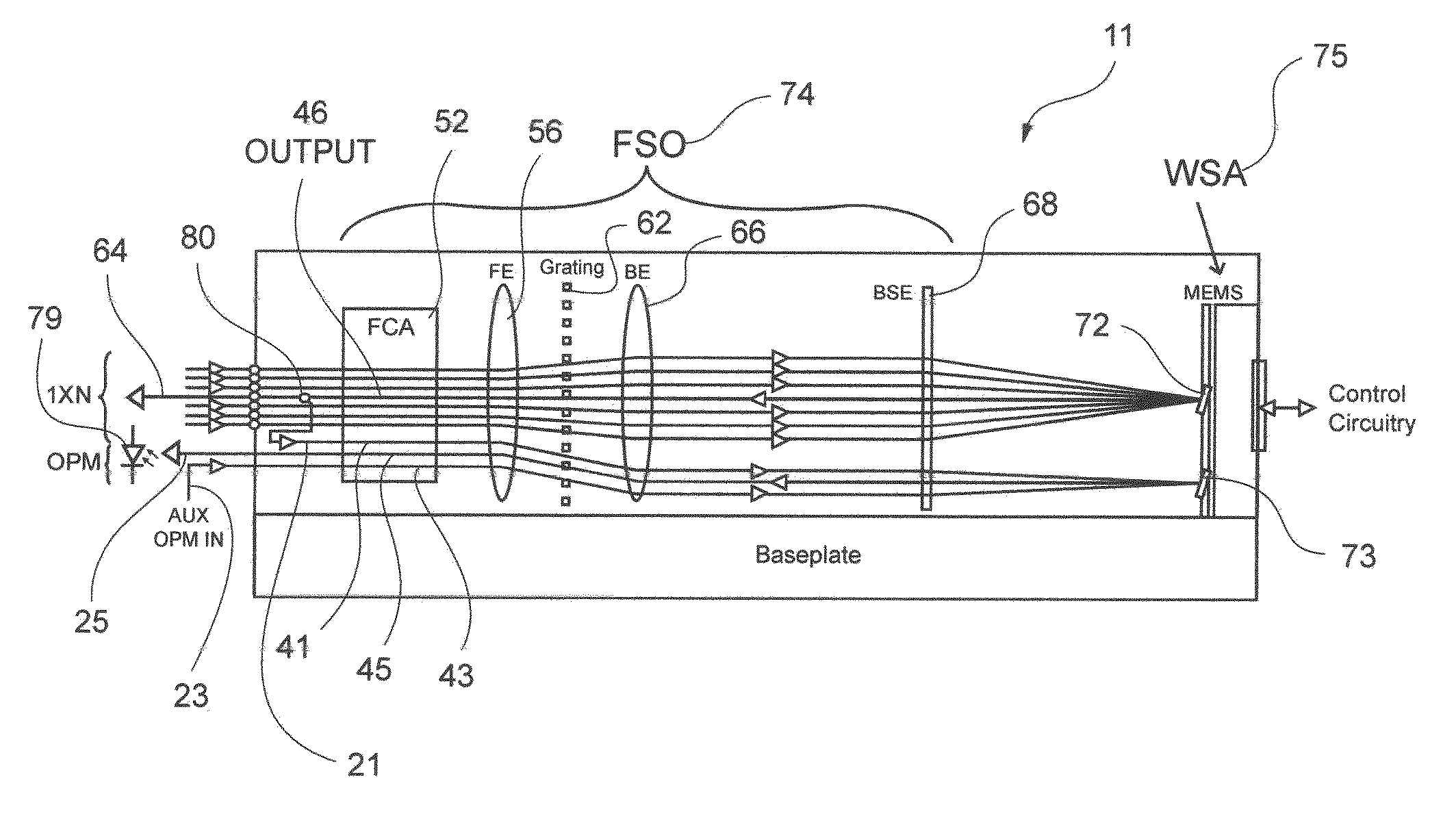
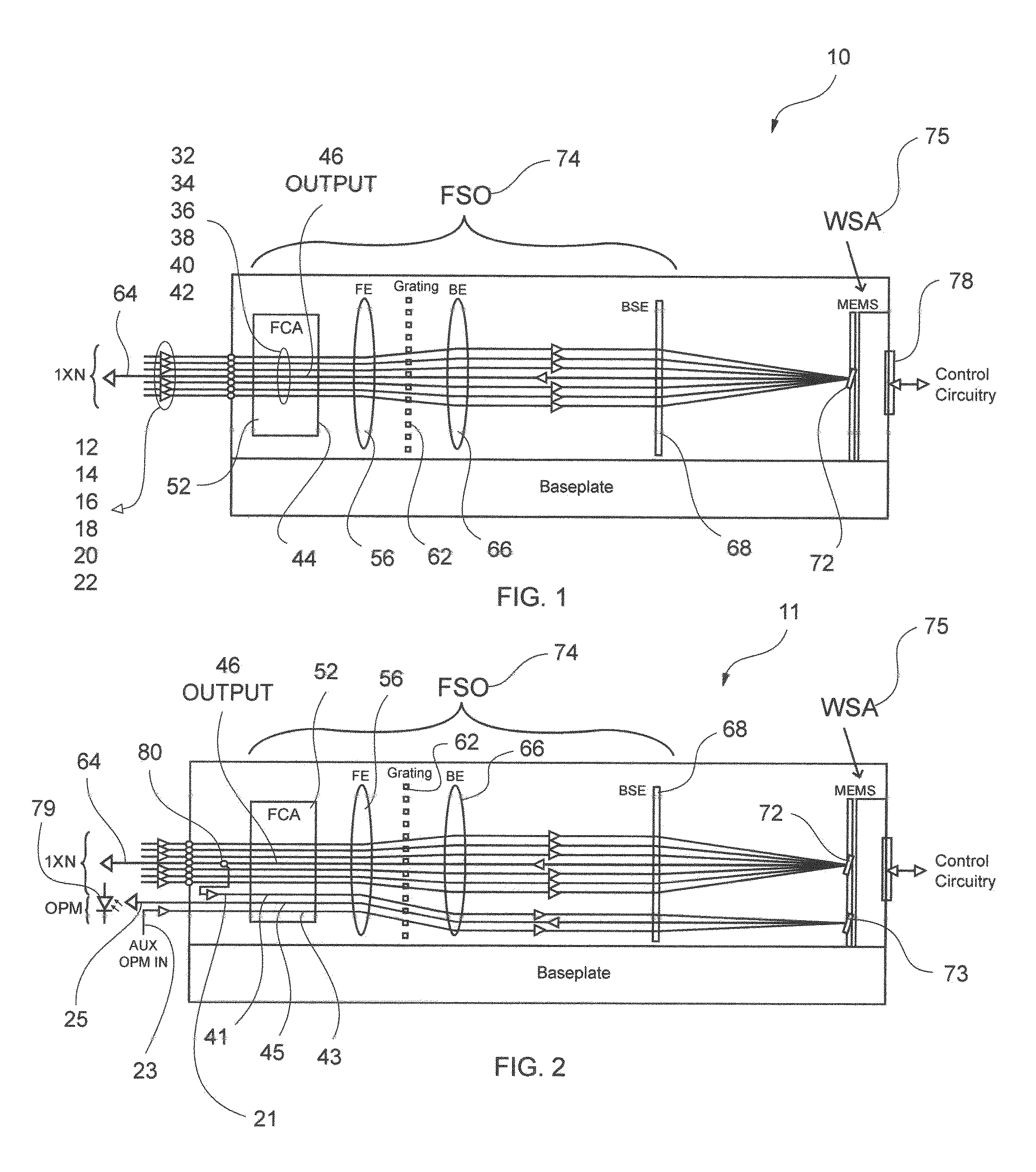
[0126]Referring now to FIG. 1, there is illustrated a schematic illustration of a six input fiber port by one output fiber port wavelength selective switch 10. However, it is emphasized that this 6×1 embodiment is illustrated only for simplicity, and that by increasing the number of input fiber ports by N, then an N×1 switch 10 is contemplated herein, wherein N represents the number of input fiber ports. Preferably, wavelength selective switch 10 can be operated in either direction, wherein N of N×1 represents N input fiber ports and one output...


PUM


Abstract

An optical system comprising a combination optical switch and monitoring system based on an array of mirrors, and a moveable reflective element co-packaged together, including discrete sets of fiber ports wherein λn from input fiber ports is focused on λn mirror via the use of shared free space optics; such as shared beam steering elements, dispersive elements, and optical elements, and discrete arrays of MEMS mirrors utilized to select and switch selected wavelengths from the input fiber port(s) to an output fiber port(s) of the optical switch, and wherein a moveable reflective element sharing the same free space optics is utilized to sweep across and reflect selected portions of the optical spectrum back to a photodetector. By correlating reflective element position with power measured, a processor can obtain a spectral plot of the wavelength band of interest, as well as calculate parameters such as center wavelength, passband shape, and OSNR.

Description

CROSS-REFERENCE AND PRIORITY CLAIM TO RELATED APPLICATION[0001]To the full extent permitted by law, the present United States Non-Provisional patent application, is a Continuation-in-Part of, and hereby claims priority to and the full benefit of, United States Non-Provisional patent application entitled “SEGMENTED PRISM ELEMENT & ASSOCIATED METHODS FOR MANIFOLD FIBEROPTIC SWITCHES,” filed on Jun. 12, 2007, now U.S. Pat. No. 7,720,329 having assigned Ser. No. 11 / 811,928, and hereby claims priority to and the benefit of United States Provisional patent application entitled “SEGMENTED PRISM ELEMENT AND ASSOCIATED METHODS FOR MANIFOLD FIBEROPTIC SWITCHES,” filed on Nov. 7, 2006, having assigned Ser. No. 60 / 857,441; United States Non-Provisional patent application entitled “BEAM STEERING ELEMENT AND ASSOCIATED METHODS FOR MANIFOLD FIBEROPTIC SWITCHES,” filed on Oct. 18, 2007, having assigned Ser. No. 11 / 975,242; United States Non-Provisional patent application entitled “BEAM STEERING ELE...

Claims


Application Information

Patent Timeline
Patent Type & Authority Patents(United States)
IPC IPC(8): G02B6/26
CPCG02B6/29311G02B6/29313G02B6/356G02B6/3588G02B6/3518G02B6/3548
Inventor NAGY, MICHAEL L.PRESLEY, HARRY W.NIELSEN, DOUGLAS A.
Owner LUMENTUM OPERATIONS LLC
Why Eureka
Try Eureka