Air-fuel ratio control apparatus of internal combustion engine and control method thereof

a technology of air-fuel ratio and control apparatus, which is applied in the direction of electrical control, process and machine control, instruments, etc., can solve the problem that the air-fuel ratio cannot be regulated in accordance with the feedback control

Inactive Publication Date: 2011-01-25
TOYOTA JIDOSHA KK
View PDF22 Cites 6 Cited by
  • Summary
  • Abstract
  • Description
  • Claims
  • Application Information

AI Technical Summary

Benefits of technology

[0016]In addition, according to the foregoing structure, the upstream side air-fuel ratio sensor can be omitted from the structure of the apparatus, which enables manufacturing costs of the apparatus on the whole to be reduced. Moreover, according to the foregoing structure, the air-fuel ratio feedback control is performed based not only on the upstream side estimated air-fuel ratio corresponding value but also on the output value of the downstream side air-fuel ratio sensor. The air-fuel ratio of the gas flowing out from the catalyst changes relatively smoothly and constantly from the so-called oxygen storage function of the catalyst (a three-way catalyst) so the output value of the downstream side air-fuel ratio sensor also changes relatively smoothly and constantly. Accordingly, air-fuel ratio feedback control that is based on the output value of the downstream side air-fuel ratio sensor is able to compensate for the constant error in the upstream side estimated air-fuel ratio corresponding value.
[0032]Moreover, the correcting device is preferably structured to correct the estimated upstream side estimated air-fuel ratio corresponding value based also on the output value of the downstream side air-fuel ratio sensor. According to this structure, the upstream side estimated air-fuel ratio corresponding value can be corrected (i.e., offset-corrected) to also reduce the constant error that it contains. Therefore, the upstream side estimated air-fuel ratio corresponding value becomes a value that more accurately indicates the air-fuel ratio of the gas discharged from the combustion chamber into the exhaust passage so the air-fuel ratio can be more appropriately feedback controlled based on the upstream side estimated air-fuel ratio corresponding value.

Problems solved by technology

Therefore, appropriate feedback control may not be performed on the air-fuel ratio if it is performed using the output value itself of the upstream side air-fuel ratio sensor.

Method used


Image

  • Air-fuel ratio control apparatus of internal combustion engine and control method thereof
  • Air-fuel ratio control apparatus of internal combustion engine and control method thereof
  • Air-fuel ratio control apparatus of internal combustion engine and control method thereof

Examples


first example embodiment

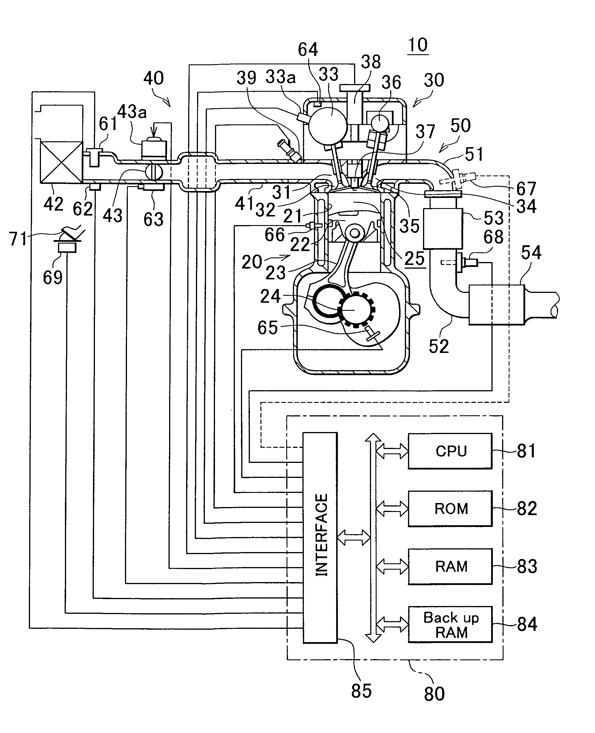
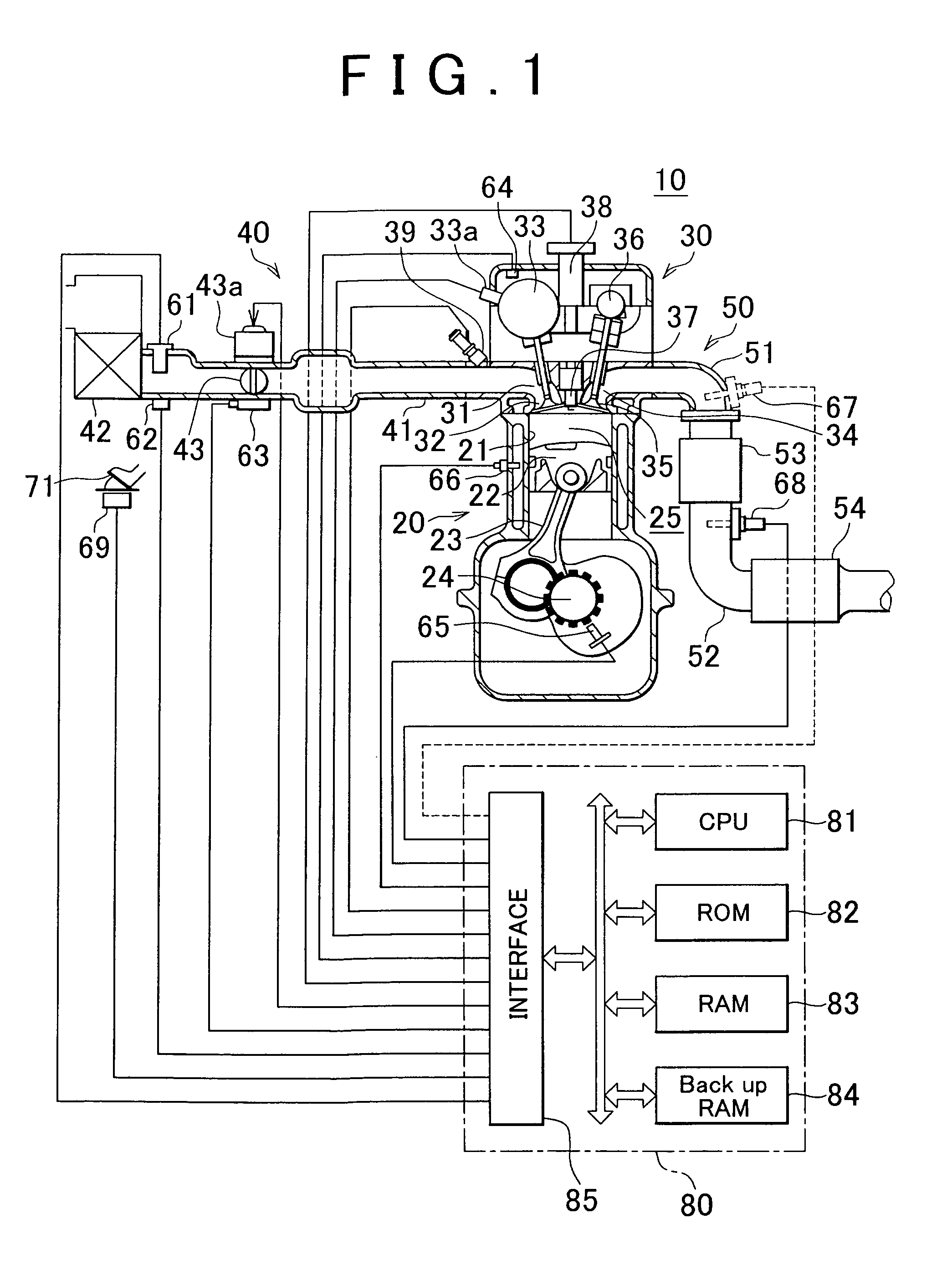
[0047]FIG. 1 is a block diagram schematically showing a system in which an air-fuel ratio control apparatus according to a first example embodiment of the invention has been applied to a four-cycle spark ignition multiple cylinder internal combustion engine 10. Although FIG. 1 shows a cross-section of only one cylinder, the other cylinders have the same structure.

[0048]This internal combustion engine 10 includes a cylinder block, a cylinder block portion 20 that includes a cylinder block lower case and an oil pan and the like, a cylinder head portion 30 which is fixed to the top of the cylinder block portion 20, an intake system 40 for supplying a gasoline air-fuel mixture to the cylinder block portion 20, and an exhaust system 50 for discharging exhaust gas from the cylinder block portion 20 outside.

[0049]The cylinder block portion 20 includes a cylinder 21, a piston 22, a connecting rod 23, and a crankshaft 24. The piston 22 moves back and forth inside the cylinder 21. This recipr...

second example embodiment

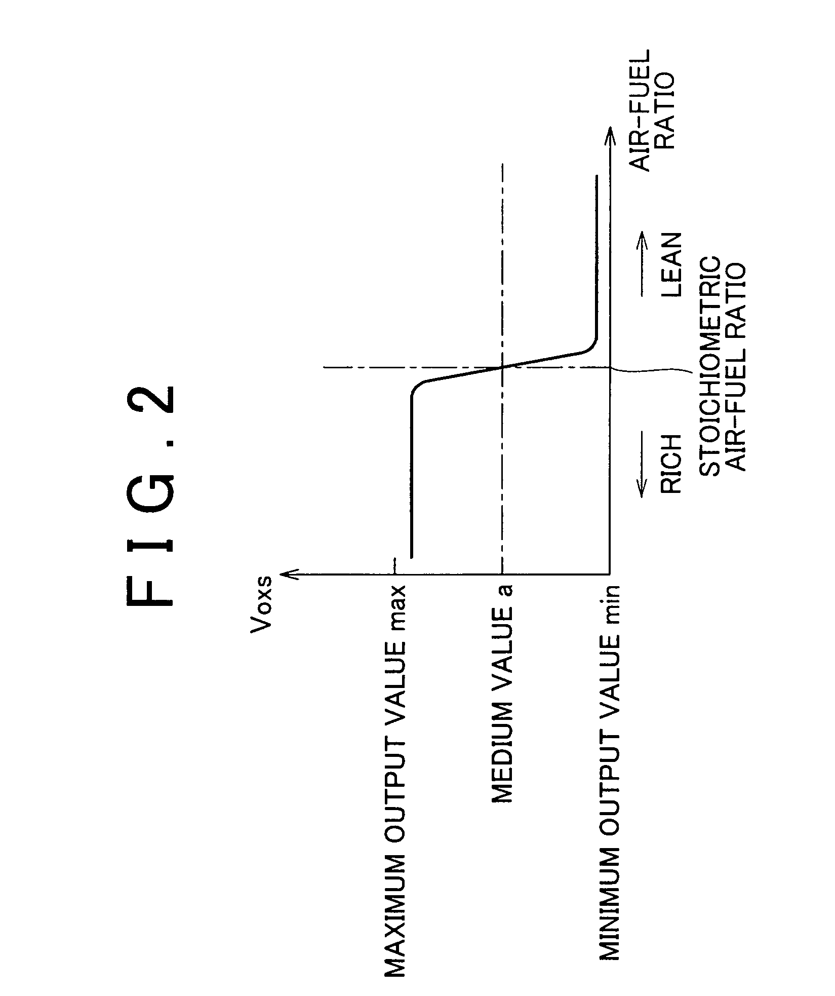
[0101]Next, an air-fuel ratio control apparatus according to a second example embodiment of the invention will be described. This second example embodiment differs from the first example embodiment described above only in that i) it is applied to an internal combustion engine provided with an air-fuel ratio sensor 67 upstream of the upstream side catalyst 53 (see the air-fuel ratio sensor 67 shown by the broken line in FIG. 1), and ii) the air-fuel ratio feedback control uses, as the estimated air-fuel ratio Afest, a value that was corrected based on a value obtained by high-pass filter processing the (air-fuel ratio corresponding to the) output value of the air-fuel ratio sensor 67, and a value obtained by low-pass filter processing the (sub-feedback control amount vafsfb that is based on the) output Voxs of the oxygen content sensor 68. Therefore, the following description will focus on these points.

[0102]This air-fuel ratio sensor 67 is a so-called limiting current oxygen content...


PUM


Abstract

An air-fuel ratio control apparatus and control method thereof performs air-fuel ratio feedback control based on an estimated value (i.e., an upstream side estimated air-fuel ratio) of an air-fuel ratio of gas discharged from a combustion chamber into an exhaust passage and an output value of an air-fuel ratio sensor downstream of a catalyst. This upstream side estimated air-fuel ratio is accurately estimated based on an operating state of the engine and a combustion state (i.e., the degree of misfire in the combustion chamber) of the engine.

Description

INCORPORATION BY REFERENCE[0001]The disclosure of Japanese Patent Application No. 2005-303887 filed on Oct. 19, 2005, including the specification, drawings and abstract is incorporated herein by reference in its entirety.BACKGROUND OF THE INVENTION[0002]1. Field of the Invention[0003]The invention relates to an air-fuel ratio control apparatus of an internal combustion engine, which controls the air-fuel ratio of gas flowing into a catalyst arranged in an exhaust passage of the internal combustion engine, and a control method of that air-fuel ratio control apparatus.[0004]2. Description of the Related Art[0005]Japanese Patent Application Publication No. JP-A-2004-183585, for example, describes a widely known air-fuel ratio control apparatus which is provided with an air-fuel ratio sensor both upstream and downstream of a catalyst (a three-way catalyst) arranged in an exhaust passage of an internal combustion engine, and feedback controls the air-fuel ratio of the air-fuel mixture su...

Claims


Application Information

Patent Timeline
Patent Type & Authority Patents(United States)
IPC IPC(8): F01N3/00F01N3/10
CPCF01N3/101F01N11/007F02D41/1439F02D41/1441F01N13/0093F01N13/009F02D41/1458F01N2560/025F02D2041/1432F02D2200/1015Y02T10/47Y02T10/22Y02T10/12Y02T10/40
Inventor WANIBE, MASAHIRO
Owner TOYOTA JIDOSHA KK
Why Eureka
Try Eureka