
Progressive cavity pump (PCP) drive head stuffing box with split seal

a technology of progressive cavity and split seal, which is applied in the direction of sealing/packing, liquid fuel engines, borehole/well accessories, etc., can solve the problems of uneven rubber strain between the major and minor diameters of the pumping section, the movement of the rotor, and the difficulty of service jobs

Inactive Publication Date: 2011-01-25
WEATHERFORD TECH HLDG LLC
View PDF25 Cites 22 Cited by
  • Summary
  • Abstract
  • Description
  • Claims
  • Application Information

AI Technical Summary

Benefits of technology

The present invention is about a mechanical seal assembly for a pump. It includes a seal housing with two semi-annular mechanical seals and a seal sleeve with two semi-annular mechanical seals. The seals have radial faces that abut each other, and they are rotationally coupled to the seal sleeve. Biasing members are used to ensure the seals are in proper engagement with each other. This design helps prevent leaks and improve the performance of the pump.

Problems solved by technology

This necessitates mounting the drive head higher, constrains the design, and means a difficult service job.
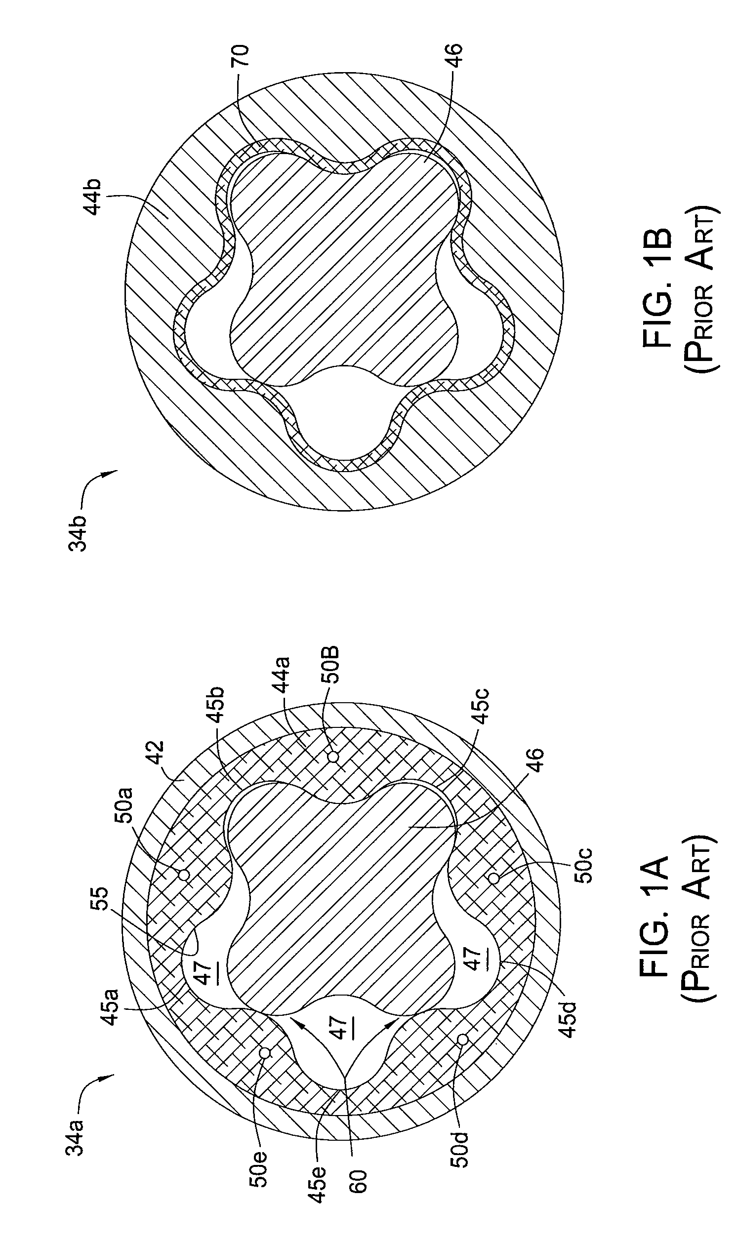
One drawback in such prior art motors is the stress and heat generated by the movement of the rotor 46 within the stator 44a.
This design can also produce uneven rubber strain between the major and minor diameters of the pumping section.
Due the abrasive sand particles present in the crude oil, premature failure of the stuffing box, particularly the mechanical seal, is common in these applications.
This costs oil companies money in service time, down time and environmental clean up.
Costs associated with stuffing box failures are one of the highest maintenance costs on many wells.
However, this means that the stuffing box is at an increased elevation requiring more service time to reach the stuffing box and increasing the risk of injury to service personnel.
This is not a good solution as the seal material flows out of the seal gland and therefore must be maintained often.

Method used


Image

  • Progressive cavity pump (PCP) drive head stuffing box with split seal
  • Progressive cavity pump (PCP) drive head stuffing box with split seal
  • Progressive cavity pump (PCP) drive head stuffing box with split seal

Examples


Embodiment Construction

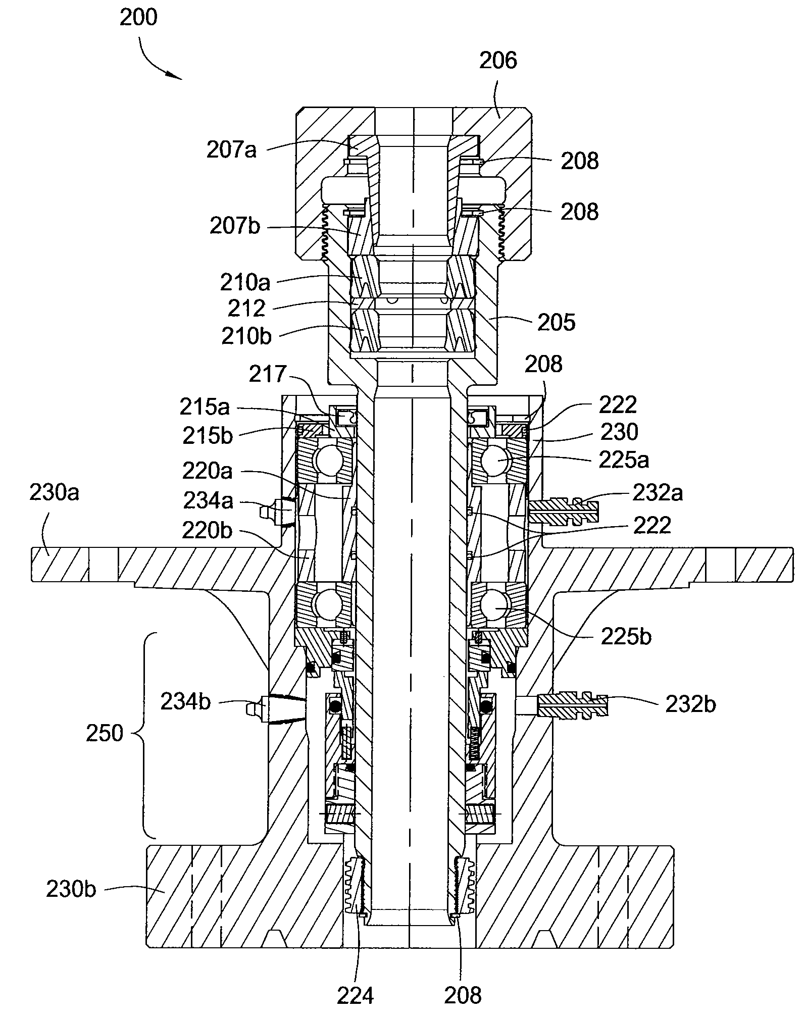
Unless otherwise specified and except for seals, all parts are made from an alloy, such as steel or stainless steel. Unless otherwise specified, all seals are made from a polymer, such as an elastomer or polyurethane (polyurethane may or may not be considered an elastomer, depending on the level of cross linking). The drive shaft 26 has been omitted for the sake of clarity. Use of the term coupling or attached herein includes direct and indirect coupling / attachment. For example, A is coupled / attached to C would include the case where A is directly coupled / attached to C and the case where A is directly coupled / attached to B which is directly coupled / attached to C.

FIG. 2 is a sectional view of a retrofit stuffing box 200 for a PC pump system, according to one embodiment of the present invention. The stuffing box 200 may replace the stuffing box 16r and be used with the PC pump system 10 of FIG. 1. The retrofit stuffing box 200 includes a rotor assembly and a stator assembly. The rotor...


PUM

PropertyMeasurementUnit
rotationaaaaaaaaaa
stressaaaaaaaaaa
heataaaaaaaaaa

Abstract

The present invention relates to a split seal for a progressive cavity pump (PCP) drive head stuffing box. In one embodiment, a mechanical seal assembly for a pump is provided. The mechanical seal assembly includes a seal housing; first and second semi-annular mechanical seals, each at least partially disposed in the seal housing bore, and a seal sleeve rotatable relative to the seal housing; third and fourth semi-annular mechanical seals, each disposed at least partially in the seal sleeve bore, at least one of the third and fourth seals rotationally coupled to the seal sleeve; and one or more biasing members biasing the mechanical seals into engagement.

Description

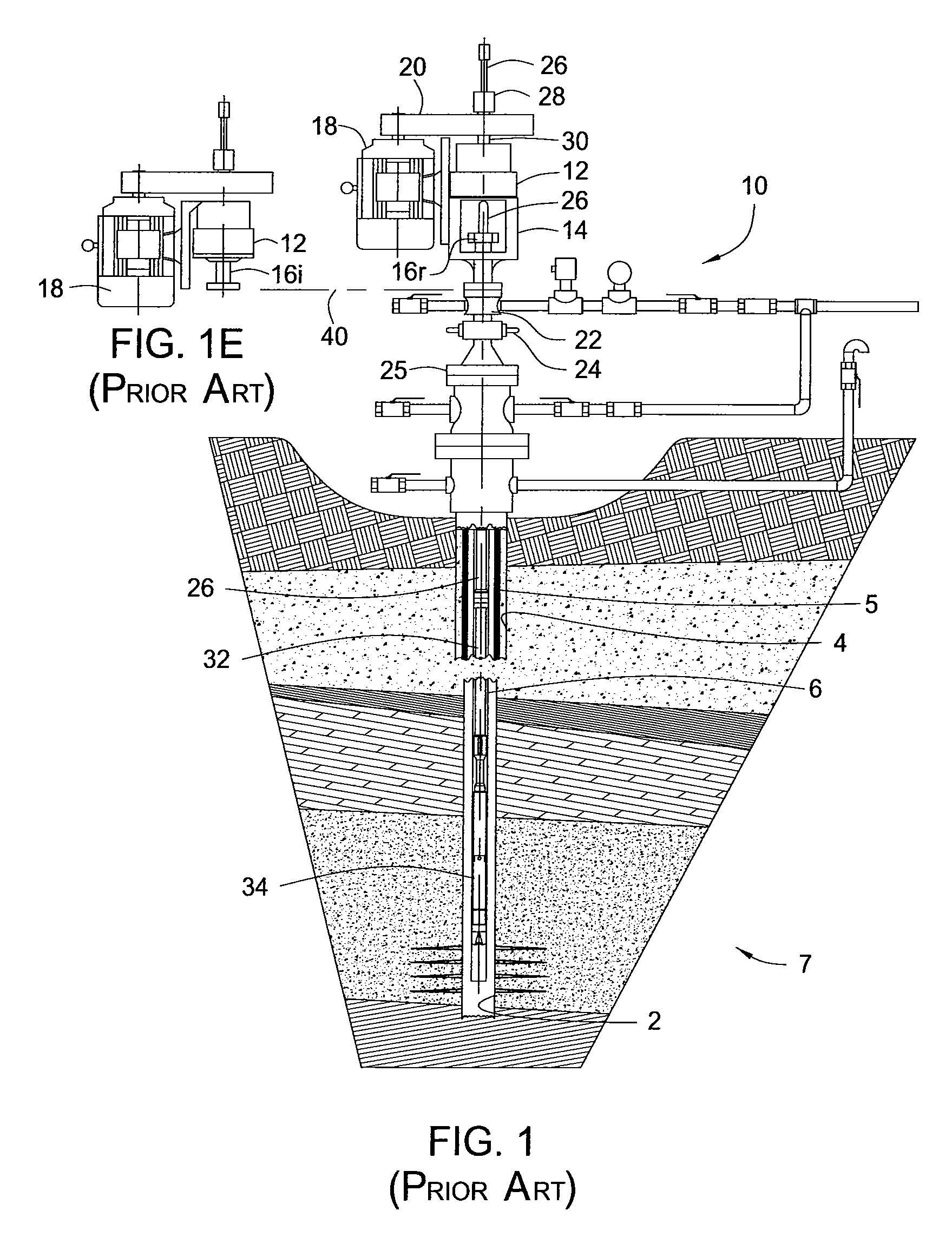
BACKGROUND OF THE INVENTION1. Field of the InventionThe present invention relates to a split seal for a progressive cavity pump (PCP) drive head stuffing box.2. Description of the Related ArtFIG. 1 illustrates a known progressing cavity pump (PCP) system 10 installed over a wellbore 2. The wellbore 2 is partially lined with casing 4 which is cemented 5 to an inner surface of the wellbore 2. The wellbore 2 extends into a hydrocarbon-bearing formation 7, such as a crude oil formation. The system 10 includes a typical progressing cavity pump drive head 12, a wellhead frame 14, a stuffing box 16, an electric motor 18, and a belt and sheave drive system 20, all mounted on a flow tee 22. Alternatively, the drive system 20 may be gear driven. The flow tee 22 is shown with a blow out preventer 24 which is, in turn, mounted on a wellhead 25. The drive head supports and drives a drive shaft 26, generally known as a “polished rod”. The polished rod 26 is supported and rotated by a polish rod c...

Claims


Application Information

Patent Timeline
Patent Type & Authority Patents(United States)
IPC IPC(8): E21B19/00
CPCF04C2/1073F04C13/007F16J15/3488F04C15/0038Y10T29/53657Y10T29/49719F04D29/10F16J15/3452F16J15/348
Inventor PARKER, CHARLES D.LANE, WILLIAM C.
Owner WEATHERFORD TECH HLDG LLC
Learn More