Component fixing method

a fixing method and component technology, applied in the direction of resist details, electrical apparatus construction details, variable capacitors, etc., can solve the problems of mechanical fixing methods that lack reliability and compactness, three kinds of fixing methods have respective problems that remain unsolved, and etc., to achieve excellent reliability and compactness, enhance vibration resistance, and overcome the difficulty of controlling the bonding strength

Inactive Publication Date: 2011-02-01
YAZAKI CORP
View PDF7 Cites 1 Cited by
  • Summary
  • Abstract
  • Description
  • Claims
  • Application Information

AI Technical Summary

Benefits of technology

[0021]In the present invention, the concave-convex mounting component (such as a film capacitor) can be surely fixed to a board such as a printed circuit board. Therefore, for example, even in the case where a large-size film capacitor is fixed to the printed circuit board of an on-vehicle equipment liable to be affected by vibrations, large stresses will not act on soldered portions and lead portions, and therefore a vibration resistance is enhanced.
[0022]And besides, unlike the conventional adhesively-bonding method, an adhesive is not used, and the problem with respect to environment-affecting substances can be solved, and at the same time difficulty involved in the control of a bonding strength can be overcome. Furthermore, the method of the invention is more excellent in reliability and compactness as compared with the conventional mechanical fixing method. Furthermore, unlike the conventional taping method, the method of the invention is excellent in economy and reliability.

Problems solved by technology

However, these three kinds of fixing methods have respective problems still remaining unsolved as described below.
First, in the adhesively-bonding method, the influence of environment-affecting substances (such as a volatile organic compound (VOC)) contained in the adhesive 5 has developed into a social problem, and besides it is difficult to control a bonding strength because of problems with respect to the amount of coating of the adhesive, coating portions, the drying time, the handling until the drying operation, etc.
The mechanical fixing method lacks in reliability and compactness.
Namely, a variation in outer size of the film capacitor 2 is large because of its producing process, and therefore it is difficult to surely fix the film capacitor.
Incidentally, in the case where the film capacitor 2 is of the encased type, that is, is housed in a case, a variation in outer size is small, but there is encountered a drawback that the overall size of the film capacitor 2 increases because of the provision of the case.
In the taping method, various disadvantages described below are encountered even when the adhesive double coated tape 6 is bonded to any portion of the lower surface of the film capacitor 2.
The taping method lacks in economy and reliability.
As a result, there is encountered an irrational situation in which although the material cost for the adhesive double coated tape 6 increases because of an increased amount of the used adhesive double coated tape 6, the bonding strength is lowered because of the reduced bonding area.
Even when the adhesive double coated tape 6 is bonded only to the electrode portions 2a of the film capacitor 2, the problems with respect to the lowered bonding strength, the resonance and the stresses can not be solved.
In addition, since the adhesive double coated tape 6 has the increased thickness, the material cost for the adhesive double coated tape 6 increases, and also the risk of increasing the amount of environment-affecting substances becomes high.
However, if the adhesive double coated tape 6 is decreased in thickness, there is a fear that the concave-convex height difference L1 of the film capacitor 2 can not be absorbed, thus resulting in defective adhesive bonding, as shown in FIG. 9C.

Method used


Image

  • Component fixing method
  • Component fixing method
  • Component fixing method

Examples


first embodiment

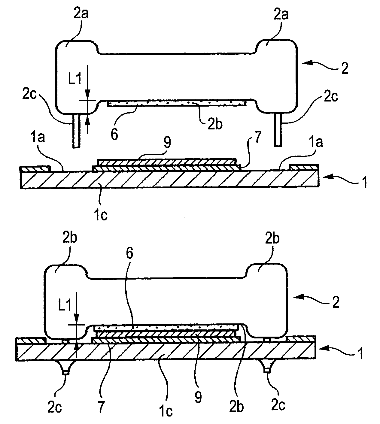
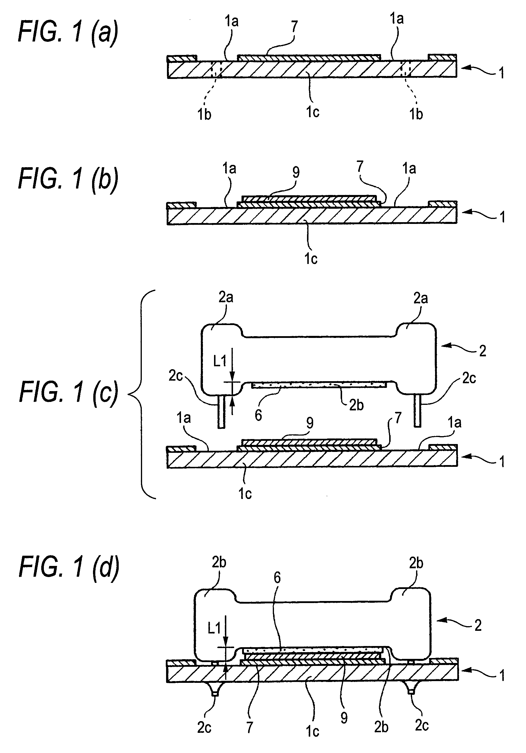
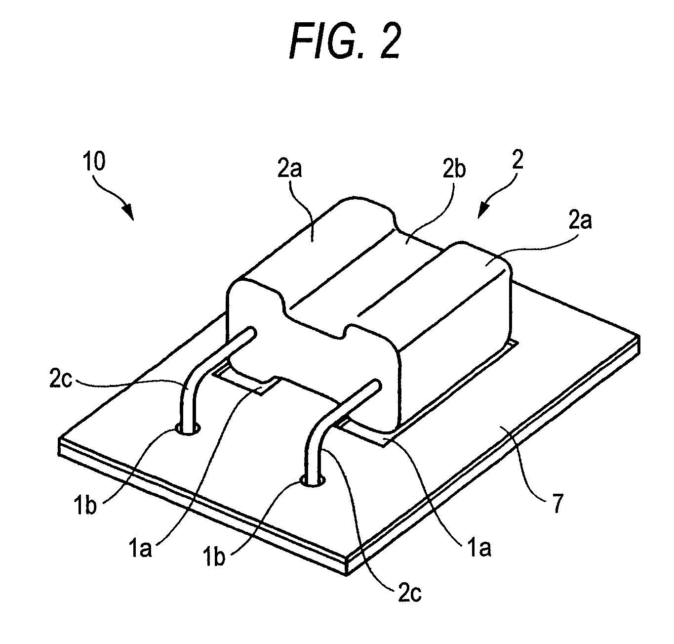
[0033]FIGS. 1A to 1D is a process view showing a first embodiment of a component fixing method of the invention, and FIG. 1A is a cross-sectional view showing a resist forming step, FIG. 1B is a cross-sectional view showing a printing step, and FIGS. 1C and 1D are cross-sectional views showing a component bonding step. FIG. 2 is a perspective view showing a circuit component, FIG. 3 is a plan view of the circuit component of FIG. 2, and FIG. 4 is a front-elevational view of the circuit component of FIG. 2.

[0034]As shown in FIGS. 2 to 4, the circuit component 10 includes a flat plate-like printed circuit board (PCB) 1, and a film capacitor 2 is mounted in a laid-down posture on the printed circuit board 1. Namely, two lead passage holes 1b are formed through the printed circuit board 1. On the other hand, the film capacitor 2 comprises a pair of electrode portions 2a, a concave portion 2b interconnecting these electrode portions 2a, and a pair of lead wires 2c extending respectively ...

second and third embodiments

[0048]FIG. 5 is a process view showing a second embodiment of a component fixing method of the invention, and FIG. 5A is a cross-sectional view showing a condition before a film capacitor is bonded to a printed circuit board, and FIG. 5B is a cross-sectional view showing a condition after the film capacitor is bonded to the printed circuit board. FIG. 6 is a process view showing a third embodiment of a component fixing method of the invention, and FIG. 6A is a cross-sectional view showing a condition before a film capacitor is bonded to a printed circuit board, and FIG. 6B is a cross-sectional view showing a condition after the film capacitor is bonded to the printed circuit board.

[0049]In the above first embodiment, the resist material is coated on the printed circuit board 1 except the electrode-opposing portions 1a thereof, and by doing so, the electrode portions 2a of the film capacitor 2 are spaced from the printed circuit board 1, and therefore these electrode portions 2a are ...


PUM

PropertyMeasurementUnit
thicknessaaaaaaaaaa
thicknessaaaaaaaaaa
concave-convex height difference L1aaaaaaaaaa

Abstract

A resist having a predetermined thickness is formed on a printed circuit board except for portions of the printed circuit board that oppose a convex portion of a component when the component is mounted on the printed circuit board. A silk screen printed layer having a predetermined thickness is formed on the resist. Thereafter, a concave portion of the component is bonded to the silk screen printed layer using double coated tape having a predetermined thickness. The component is mounted such that the convex portions of the component oppose the portions of the printed circuit board that do not have a resist formed thereon. The sum of the thicknesses of the resist, the silk screen printed layer and the double coated tape is larger than a height difference between the concave portion and the convex portion of the component.

Description

BACKGROUND OF THE INVENTION[0001]1. Field of the Invention[0002]This invention relates to a component fixing method suitably used for mounting a film condenser (film capacitor) (used in a high-voltage circuit) on a printed circuit board (PCB).[0003]2. Description of the Related Art[0004]FIG. 7 show a conventional adhesively-bonding method, and FIG. 8 shows a conventional mechanical fixing method. FIG. 9 shows conventional taping methods, and FIG. 9A is a cross-sectional view showing a condition in which an adhesive double coated tape is bonded to a lower surface of a film capacitor over an entire area thereof, and FIG. 9B is a cross-sectional view showing a condition in which an adhesive double coated tape is bonded only to a lower surface of a concave portion of a film capacitor, and FIG. 9C is a cross-sectional view showing a condition in which a thin adhesive double coated tape is used.[0005]Film capacitors of this kind must be increased in size so as to withstand a high pressure...

Claims


Application Information

Patent Timeline
Patent Type & Authority Patents(United States)
IPC IPC(8): H05K3/30
CPCH05K3/306H05K3/305H05K3/3447H05K3/3452H05K2201/10015H05K2201/10462Y10T29/49144H05K2201/2036H05K2203/0191H05K2203/0588Y10T29/43Y10T29/4913Y10T29/49165H05K2201/10598
Inventor KAWAMURA, YOSHIHIRO
Owner YAZAKI CORP
Why Eureka
Try Eureka