Ultrasonic transducer, ultrasonic transducer array and ultrasound endoscope apparatus

a transducer and array technology, applied in the field of electroradial scanning type ultrasonic transducers, can solve the problems of reducing durability, affecting image quality, and affecting the use of flexible materials,

Active Publication Date: 2011-02-01
OLYMPUS CORP
View PDF34 Cites 6 Cited by
  • Summary
  • Abstract
  • Description
  • Claims
  • Application Information

AI Technical Summary

Problems solved by technology

This causes a significant ill influence on image quality when compared to large scale ultrasonic transducers such as sonar in which a displacement of a few tens of micrometers at a joint is not significant.
However, if the joint is adhered with the backing member, durability is undermined when performing sterilization treatment via chemicals or heating.
As such, connection of a joint with the backing member material results in varying characteristics and leads to reduced durability due to the use of a flexible material.
In an ultrasonic transducer array symmetrically formed for obtaining a good acoustic characteristics such as the radial system ultrasonic transducer array 1120 shown in FIG. 4, the individual ultrasonic transducers are formed into a circular pattern by mutually connecting the ultrasonic transducers at both ends, making it difficult to identify ultrasonic transducers at the ends; this results in a difficulty in identifying a specific ultrasonic transducer.
Also, in the convex system ultrasonic transducer array and linear system ultrasonic transducer array, if an ultrasonic transducer array used for an ultrasound endoscope apparatus is very small, it is difficult to count the ultrasonic transducers and hence difficult to identify a predefined ultrasonic transducer.
Also, the ultrasonic transducer formed by fixing a flexible support member to a damper member with an adhesive, such as the ultrasonic probe noted in patent document 1, has been faced with the possibility of occurrences of performance problems such as an elongated pulse width caused by the adhesive layer being placed in between the support member and the damper member.
Because of this, there is a possibility that a residual stress in the elastic member will cause a broken electrical connection or other such failure.
Furthermore, when fixing a soft member with an adhesive, the thickness of the adhesive layer varies and the form of the member cannot be maintained at a high accuracy; this is different from the case of adhering hard members to each other, and therefore it has been difficult to obtain the desired accuracy of the form.
However, common board materials such as glass epoxy board used for the usage described above have been faced with difficulties in improving the accuracy of the machining process because of minute changes in form as a result of the glass fiber coming off the resin at an edge part that is being processed for a feature.
In addition, polyimide has a low rigidity and a low adhesive property, and is thus faced with the problem of being unsuitable for use for a frame.

Method used


Image

  • Ultrasonic transducer, ultrasonic transducer array and ultrasound endoscope apparatus
  • Ultrasonic transducer, ultrasonic transducer array and ultrasound endoscope apparatus
  • Ultrasonic transducer, ultrasonic transducer array and ultrasound endoscope apparatus

Examples


Embodiment Construction

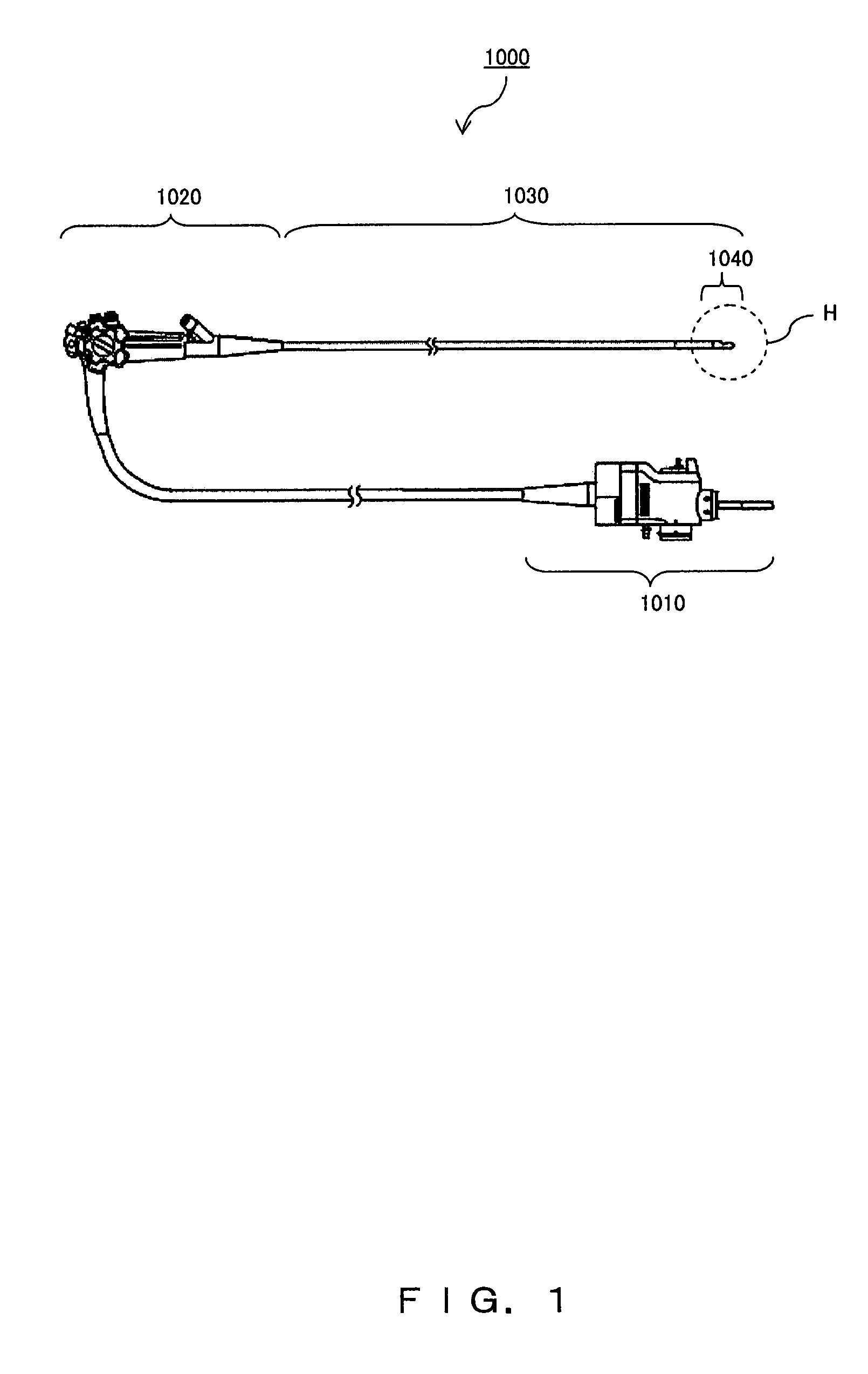
[0140]FIG. 6 is a diagram showing an external configuration of an ultrasound endoscope according to the present embodiment. The ultrasound endoscope 1 comprises an operation part 6 on the base end of a slender insertion part 2. A universal cord 7 to be connected to a light source apparatus (not shown herein) extends from the side part of the operation part 6.

[0141]The insertion part 2 comprises the connection of, in sequence starting at the head part, a head part 3, a bendable part 4 allowing the insertion part to bend freely, and a flexible tube part 5 having flexibility. The operation part 6 is equipped with a bending operation knob 6a so that the bendable part 4 can be bent by operating the bending operation knob 6a.

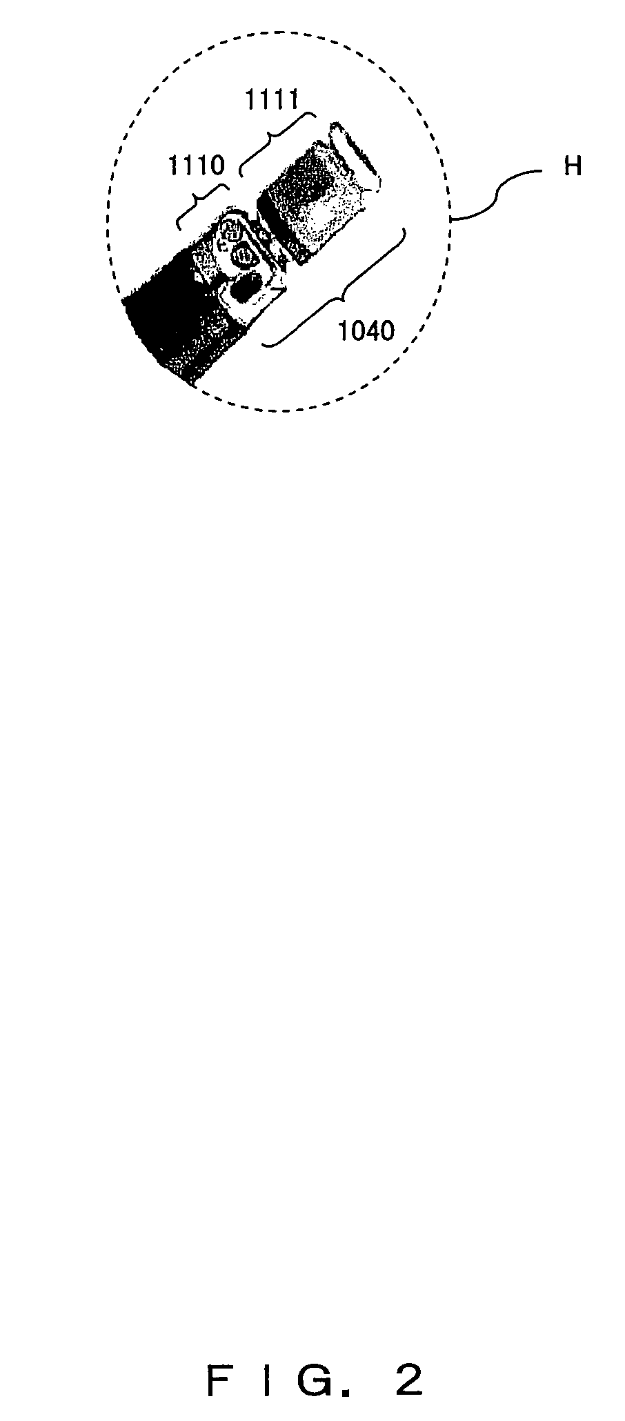
[0142]FIG. 7 is an enlarged diagram of the head part 3 of the ultrasound endoscope 1 shown in FIG. 6. The head part 3 is equipped with an ultrasonic transducer 10 (or an ultrasonic transducer array) enabling electronic radial type scanning, and an inclined part 12 is...


PUM


Abstract

An ultrasonic transducer arraying at even intervals ultrasonic transducers for transmitting and receiving ultrasonic waves and layering a plurality of acoustic matching layers on them, comprising an transducer shape forming member made of a fiber-reinforced thermosetting PPE for filling a gap formed on the side face of the ultrasonic transducer with the same material as that of the acoustic matching layer, mixing a colorant in a division member adjacent to a predefined ultrasonic transducer from among a plurality of ultrasonic transducers, and arraying the plurality thereof.

Description

TECHNICAL FIELD[0001]The present invention relates to an electronic radial scanning type ultrasonic transducer.BACKGROUND ART[0002]In conventional medical practice there exists an ultrasonic diagnosis apparatus that repeatedly transmits an ultrasonic pulse into a live body from an ultrasonic transducer, then receives an echo of the ultrasonic pulse reflected from the live body by the same or separately equipped ultrasonic transducer, and then gradually shifts the direction of transmission and reception of the ultrasonic pulse, thereby displaying information collected from a plurality of directions within the live body as a visible ultrasonic tomography image.[0003]The ultrasonic transducers used for such an ultrasonic diagnosis apparatus or the like include an array type ultrasonic transducer employing an electronic scanning system that arrays a plurality of piezoelectric elements regularly. This ultrasonic transducer includes a radial array type that arrays a plurality of piezoelec...

Claims


Application Information

Patent Timeline
Patent Type & Authority Patents(United States)
IPC IPC(8): H01L41/08
CPCA61B8/12A61B8/4281A61B8/445B06B1/0633A61B8/4483A61B8/4494
Inventor SAWADA, YUKIHIKOWAKABAYASHI, KATSUHIROMIZUNUMA, AKIKOIMAHASHI, TAKUYASATO, SUNAO
Owner OLYMPUS CORP
Why Eureka
Try Eureka