
Rod and cone response sensor

a response sensor and rod-shaped technology, applied in the field of imager devices, can solve the problems of reducing the transmissivity of imagers, unable to take advantage of the nir energy present, and imagers suffering from the transmissive loss of color filters

Inactive Publication Date: 2011-02-01
APTINA IMAGING CORP
View PDF32 Cites 45 Cited by
  • Summary
  • Abstract
  • Description
  • Claims
  • Application Information

AI Technical Summary

Problems solved by technology

This is largely due to the color filters themselves, which diminish transmissivity.
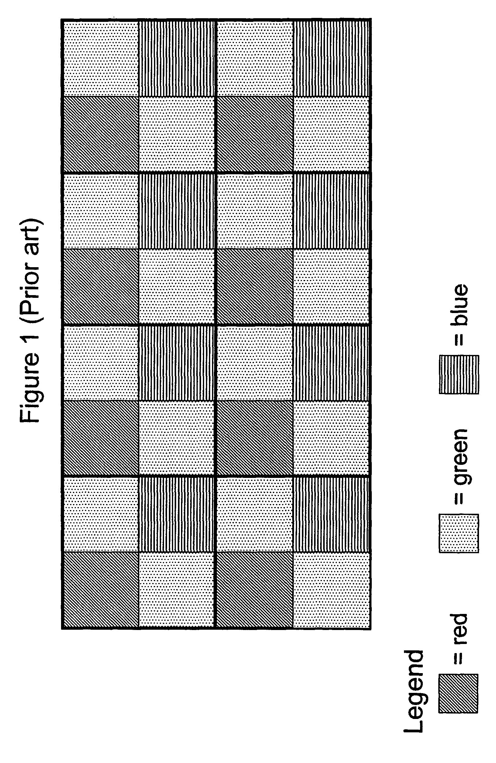
However, in low light conditions, not only does the imager suffer from the color filter transmissive losses, but it also cannot take advantage of the NIR energy present without an additional mechanism to remove the NIR filter from the pixel array.
However, monochromatic imagers are incapable of capturing color information of images.

Method used


Image

  • Rod and cone response sensor
  • Rod and cone response sensor
  • Rod and cone response sensor

Examples


Embodiment Construction

[0020]In the following detailed description, reference is made to the accompanying drawings which form a part hereof, and in which is shown by way of illustration specific embodiments in which the invention may be practiced. These embodiments are described in sufficient detail to enable those skilled in the art to practice the invention, and it is to be understood that other embodiments may be utilized, and that structural, logical and electrical changes may be made without departing from the spirit and scope of the present invention.

[0021]The term “substrate” is to be understood as a semiconductor-based material including silicon, silicon-on-insulator (SOI) or silicon-on-sapphire (SOS) technology, doped and undoped semiconductors, epitaxial layers of silicon supported by a base semiconductor foundation, and other semiconductor structures. Furthermore, when reference is made to a “substrate” in the following description, previous process steps may have been utilized to form regions ...


PUM


Abstract

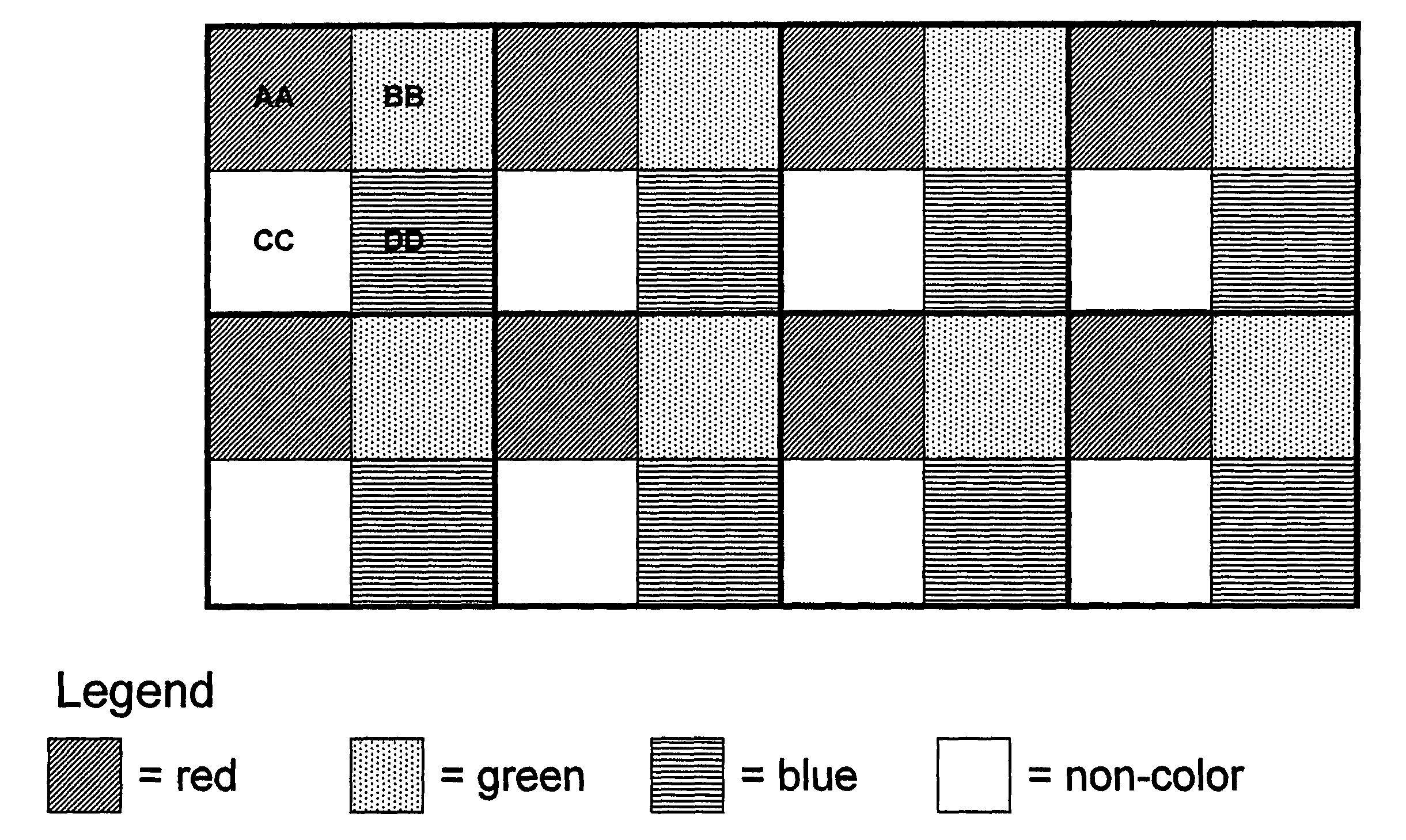
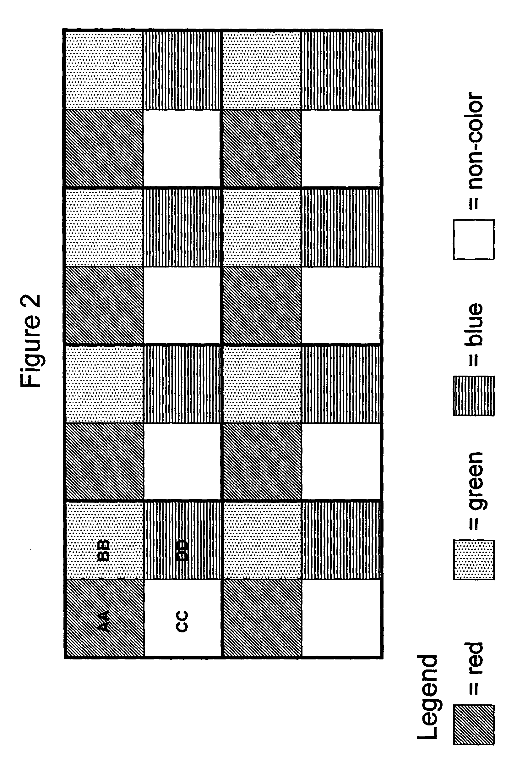
An imager having color sensitivity in any lighting condition is provided by replacing at least one of the green color filtered pixels in a Bayer pattern array with an non-color filtered pixel and providing a different integration period for each color channel. When replacing a color filtered pixel with a non-color filtered pixel, the benefits of both color sensitivity and light sensitivity may be harnessed by providing the color filtered pixels with a longer integration period than the non-color filtered pixels. Color information may be interpolated by performing subtraction logic using non-color and color filter information from adjacent pixels in back-end processing. Integration times for each color channel can be adapted to minimize filter transmission and sensor absorption differences within each frame of data. Temporal displacement of colors of moving objects by having different integration periods may be corrected in back-end processing. Back-end processing may also correct motion blur.

Description

FIELD OF THE INVENTION[0001]This invention relates to imager devices and, in particular, to improved light sensitivity in pixel arrays.BACKGROUND OF THE INVENTION[0002]Humans perceive light energy of varying wavelengths as color, detected by two types of light-sensitive receptors in the retina of the eye, rod cells and cone cells. The rod cells detect only the quantity of light, working at even low light levels with fewer photons, also known as night-vision. They are stimulated by the intensity of light and are responsible for perceiving the size, shape, and brightness of visual images, but do not perceive color and fine detail. The cone cells, of which there are three types, each capable of detecting a different range of wavelength of light being received, require hundreds of photons to activate them. They are less sensitive to low illumination levels but provide color information. Of the three types of cones, each one contains a distinctive type of pigment, absorbing red light, gr...

Claims


Application Information

Patent Timeline
Patent Type & Authority Patents(United States)
IPC IPC(8): H04N5/335H04N5/353H04N9/04H04N5/3745H04N9/07
CPCH04N5/332H04N9/045H04N23/11H04N25/131H04N25/136H04N23/843H04N25/00H04N23/10
Inventor GALLAGHER, PAUL K.
Owner APTINA IMAGING CORP
Learn More