System for detecting and reducing noise via a microphone array

a microphone array and microphone technology, applied in the field of system for detecting noise, can solve the problems of low signal level at the microphone, reduced signal to noise ratio (snr) in comparison to a handset system, and high ambient noise level, so as to reduce noise and reduce noise.

Active Publication Date: 2011-02-01
CERENCE OPERATING CO
View PDF15 Cites 35 Cited by
  • Summary
  • Abstract
  • Description
  • Claims
  • Application Information

AI Technical Summary

Benefits of technology

[0012]This application provides a system for detecting noise, particularly uncorrelated noise, via a microphone array. The system also provides a method for detecting noise, particularly uncorrelated noise, via a microphone array. The application also provides a system for reducing noise, particularly uncorrelated noise, received by a microphone array connected to a beamformer. The system also provides a method for reducing noise, particularly uncorrelated noise, received by a microphone array connected to a beamformer. The application further provides for receiving microphone signals emanating from microphones of a microphone array and decomposing each microphone signal into frequency sub-band signals. A time dependent measure based on the frequency sub-band signals may be determined for each microphone signal. A time dependent criterion function may be determined as a predetermined statistical function of the time dependent measures. The criterion function may be evaluated according to a predetermined criterion to detect noise.
[0013]The application also provides a system for reducing noise in a microphone signal received by a microphone array, where a beamformer is configured to receive a microphone signal from the microphone array. The beamformer outputs a beamformer output signal, which may be replaced with a modified beamformer output signal.
[0014]The application also provides for a computer program product with a computer useable medium having a computer readable code embodied in the medium for detecting and reducing uncorrelated noise. The computer readable program code in the computer program product further may include computer readable program code for causing the computer to detect uncorrelated noise, as well as computer readable program code for causing the computer to reduce uncorrelated noise.

Problems solved by technology

However, in handsfree systems, the signal to noise ratio (SNR) usually is deteriorated (i.e., reduced) in comparison to a handset system.
This is mainly due to the distance between the microphone and the speaker, and the resulting low signal level at the microphone.
Furthermore, a high ambient noise level is often present, requiring utilization of methods for noise reduction.
However, achieving a significant improvement in SNR with simple DSBF requires an impractical number of microphones, even under idealized noise conditions.
However, traditional adaptive beamformers are not necessarily as well suited for use in speech applications where, for example, the signal of interest has a wide bandwith, the signal of interest is non-stationary, interfering signals also have a wide bandwith, interfering signals may be spatially distributed, or interfering signals are non-stationary.
However, obtaining a noise measurement that is free from signal leakage, especially in reverberant environments, is generally where the difficulty lies in implementing a robust and effective GSC.
The wind pressure and air turbulences may deviate the membrane of the microphone considerably, resulting in strong pulse-like disturbances, which may be known as wind noise or Popp noise.
In vehicles, this problem may arise if the fan is switched on or in the case of the open top of a cabriolet.
However, the effectiveness of such a wind shield depends on its size and, hence, increases the overall size of the microphone.
A large microphone is often undesired because of design reasons and lack of space.
Because of these and other reasons, many microphones are not equipped with an adequate wind shield, thereby resulting in poor speech quality for a handsfree device and low speech recognition rate of a speech control system.

Method used


Image

  • System for detecting and reducing noise via a microphone array
  • System for detecting and reducing noise via a microphone array
  • System for detecting and reducing noise via a microphone array

Examples


Embodiment Construction

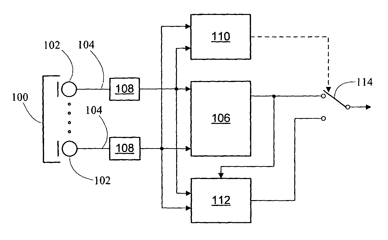
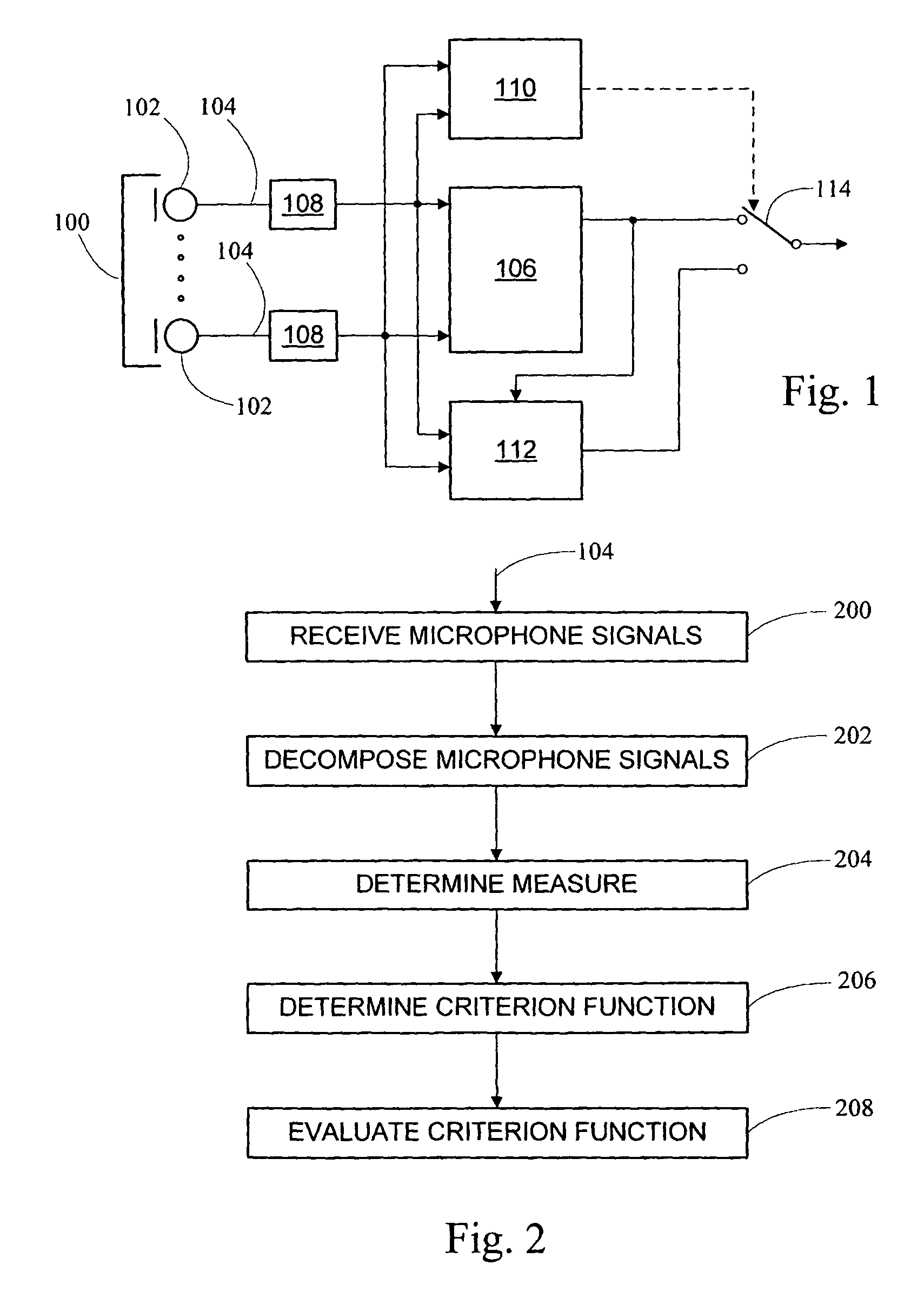
[0022]In FIG. 1, an example of a system for reducing or suppressing noise is shown. A microphone array 100 with at least two microphones 102 is shown. While a particular arrangement of the microphones 102 in the microphone array 100 is shown, different arrangements of the microphones 102 are possible. For example, the microphones 102 may be placed in a row, where each microphone 102 has a predetermined distance to its neighbors. For example, the distance between microphones 102 may be approximately 5 cm. Depending on the application, the microphone array 100 may be mounted at a suitable place. For example, in the case of a vehicle or a vehicle cabin, the microphone array 100 may be mounted in the driving mirror near the roof of the vehicle, or in the headrest. In this application, the term vehicle includes an automobile, motorcycle, spaceship, airplane and / or train, or any other means of conventional or unconventional transportation.

[0023]Microphone signals 104 emanating from the mi...


PUM


Abstract

A system for detecting noise in a signal received by a microphone array and a method for detecting noise in a signal received by a microphone array is disclosed. The system also provides for the reduction of noise in a signal received by a microphone array and a method for reducing noise in a signal received by a microphone array. The signal to noise ratio in handsfree systems may be improved, particularly in handsfree systems present in a vehicular environment.

Description

PRIORITY CLAIM[0001]This application claims the benefit of European Patent Application No. 04006445.3, filed Mar. 17, 2004. The disclosure of the above application is incorporated in its entirely herein by reference.BACKGROUND OF THE INVENTION[0002]1. Technical Field[0003]This application is directed to a system for detecting noise, particularly uncorrelated noise, via a microphone array and to a system for reducing noise, particularly uncorrelated noise, received by a microphone array connected to a beamformer.[0004]2. Related Art[0005]In different areas, handsfree systems are used for many different applications. In particular, handsfree telephone systems and speech control systems are getting more and more common for vehicles. This may be due to a perceived increase in comfort and safety that is obtained when using handsfree systems. Particularly in the case of vehicular applications, one or several microphones can be mounted in the vehicular cabin. Alternatively, a user can be p...

Claims


Application Information

Patent Timeline
Patent Type & Authority Patents(United States)
IPC IPC(8): H04B15/00H04R3/00H03B29/00H04R1/40G10L15/20G10L21/0232G10L21/0264H04M9/08
CPCH04R3/005H04R29/005H04R2410/07H04R2430/20G10L21/0216G10L2021/02166G10L21/0232D06M11/00D06M11/42D06M2200/25D06M2200/12D10B2401/021D10B2401/13D10B2401/22D10B2505/18
Inventor BUCK, MARKUSHAULICK, TIM
Owner CERENCE OPERATING CO
Why Eureka
Try Eureka