Imaging system and related techniques

a technology of imaging system and imaging system, applied in the direction of patient positioning for diagnostics, instruments, applications, etc., can solve the problems of reducing the ability of the system to image relatively, inducing vibration in the apparatus being moved, etc., to improve the freedom to position objects and reduce the amount of vibration induced by source movement

Inactive Publication Date: 2011-02-08
THE GENERAL HOSPITAL CORP
View PDF50 Cites 17 Cited by
  • Summary
  • Abstract
  • Description
  • Claims
  • Application Information

AI Technical Summary

Benefits of technology

[0008]The variable magnification tomography technique of the present invention, on the other hand, employs motion along an axis which is typically substantially normal to an imaging plane of a detector disposed on an opposite side of the object from the source. Since the source need only move toward and away from the object being imaged, translational movement of the source (with respect to the object being imaged) is not required. Since transitional movement of the source is not required, the amount of vibration induced by source movement is lowered which results in the system being able to image relatively small features of an object.
[0009]Also, using source and / or detector and / or object motion which is in the same direction as the direction in which the source signal is emitted can eliminate the need to move the source translationally (e.g. along an arc-shaped path about the object being imaged). Since the relative motion of the source and / or object and / or detector is in a single line or direction, this improves the freedom to position objects or patients in desirable configurations for imaging and for procedures (biopsy, needle-localization, ultrasound, etc.).
[0010]In accordance with a further aspect of the present invention, an imaging technique includes operating a source and a detector to generate a first projection image of an object, moving at least one of the source, the object and the detector in a direction which changes the distance between the object and at least one of the source and the detector and operating the source and a detector to generate another projection image of the object corresponding to a magnified or de-magnified image of the object. With this particular arrangement, an imaging technique which provides projection images which can be used to generate three dimensional tomographic images without translating the source, object or detector is provided. By changing the distance between the source and / or detector and the object being imaged, a divergent beam passes through the tissues at differing angles depending on the distance of the x-ray source from the structures in the objects being imaged. These images can then by synthesized into tomographic slices. Thus, a three-dimensional image can be generated without moving the source and / or detector in an arc-shape path about the object and without requiring or using any translation motion of the source, object and / or detector.

Problems solved by technology

This is generally cumbersome and tends to induce vibrations in the apparatus being moved.
The vibrations reduce the ability of the system to image relatively small features of an object.

Method used


Image

  • Imaging system and related techniques
  • Imaging system and related techniques
  • Imaging system and related techniques

Examples


Embodiment Construction

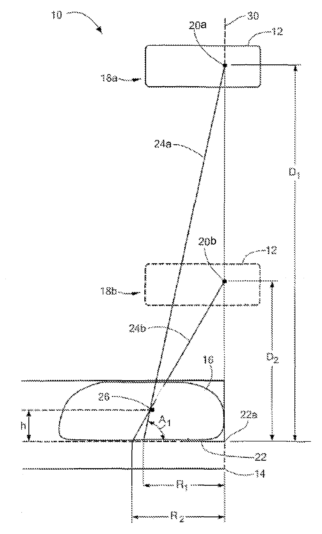
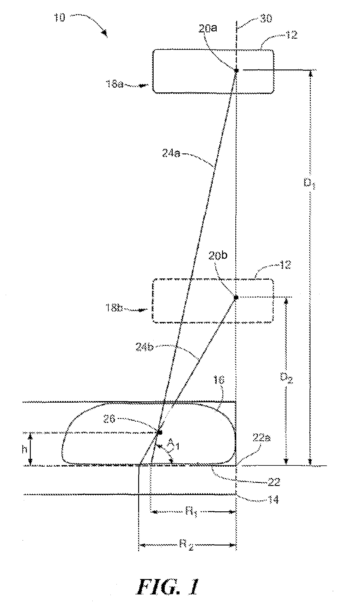
[0019]Before describing an imaging system and operations performed to generate images, some introductory concepts and terminology are explained.

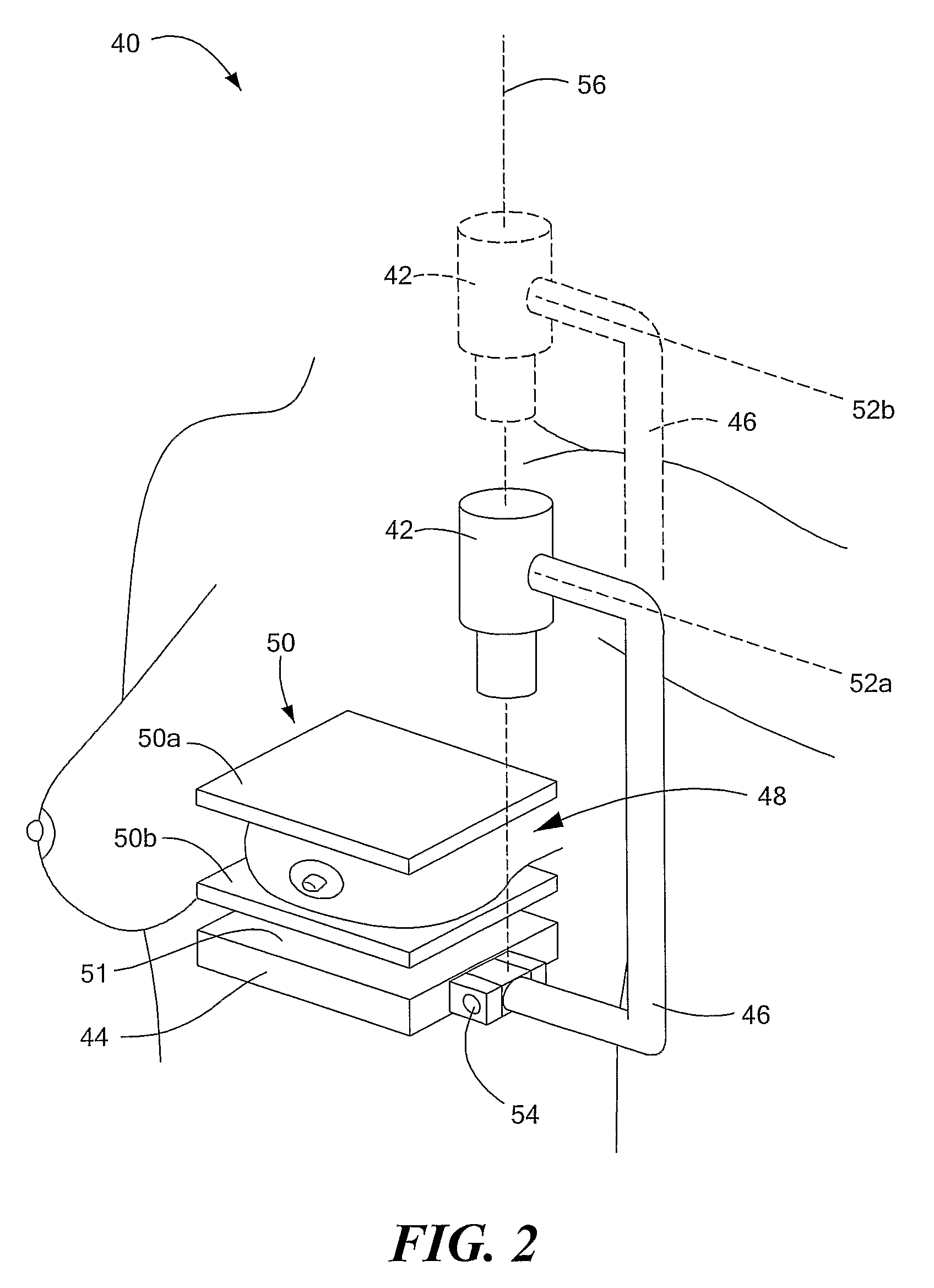
[0020]It should be appreciated that the systems and techniques described herein can be used in a variety of different applications such as breast imaging, therapeutic applications, photoacoustic applications, skin imaging and other applications.

[0021]With the above in mind, it should be appreciated that as used herein, the term “source” refers to any type of source which emits a signal which is received by an appropriate detector. Different types of sources can emit different types of signals and for any particular application, those of ordinary skill in the art will recognize how to select a particular type of source (and a corresponding detector) suitable for the particular application.

[0022]It should also be appreciated that, in an effort to promote clarity in the description of the claimed subject matter, specific reference and examples ...


PUM

PropertyMeasurementUnit
angleaaaaaaaaaa
depthaaaaaaaaaa
view-anglesaaaaaaaaaa

Abstract

An imaging method and apparatus is described in which distances between a source and an object are changed and projection images are generated at each of the different distances.

Description

CROSS REFERENCE TO RELATED APPLICATIONS[0001]This application is a U.S. National Stage of International Patent Application No. PCT / US2006 / 038828 filed Oct. 4, 2006, and published in the English language, which application claims the benefit of U.S. Provisional Patent Application No. 60 / 728,546 filed on Oct. 19, 2005 under 35 U.S.C. §119(e), which applications are hereby incorporated herein by reference in their entirety.FIELD OF THE INVENTION[0002]This invention relates generally to imaging systems and techniques and more particularly to systems and techniques methods for generating tomographic images.BACKGROUND OF THE INVENTION[0003]As is known in the art, tomosynthesis is a technique for acquiring and processing a series of projection measurements of an object into three dimensional (3D) slice information. In breast tomosynthesis, for example, the breast is held immobile, while a source (such as an X-ray tube) and / or the detector are moved through a series of positions on an arc t...

Claims


Application Information

Patent Timeline
Patent Type & Authority Patents(United States)
IPC IPC(8): A61B6/00G01N23/00
CPCA61B6/025A61B6/4233A61B6/466A61B6/5223A61B6/588A61B6/589A61B6/502A61B6/027A61B6/4291
Inventor KOPANS, DANIEL B.MOORE, RICHARD H.
Owner THE GENERAL HOSPITAL CORP
Why Eureka
Try Eureka