Turbine airfoil with continuous curved diffusion film holes

a technology of diffusion film and turbine airfoil, which is applied in the direction of engine fuction, machine/engine, engine manufacturing, etc., can solve the problems of limiting the operating temperature of the engine, low film cooling effectiveness, and dilution of coolant, so as to improve the film cooling effectiveness of the film cooling hole, improve the film coverage, and improve the effect of film cooling effectiveness

Inactive Publication Date: 2011-02-15
FLORIDA TURBINE TECH
View PDF15 Cites 58 Cited by
  • Summary
  • Abstract
  • Description
  • Claims
  • Application Information

AI Technical Summary

Benefits of technology

[0009]An improvement in the film cooling effectiveness for a film cooling hole can be produced by the use of a film hole geometry of the present invention. A film cooling hole includes a three dimensional continuous curved diffusion film hole. The three dimensional nature of the film cooling hole of the present invention is described by a series of ellipses of increasing eccentricity tangent at the point corresponding to the minor axis. The film hole construction will allow for radial diffusion of the stream-wise oriented flow and combine the best aspects of both radial and stream-wise straight holes. The

Problems solved by technology

However, the turbine parts—especially the first stage stator vanes and rotor blades—are exposed to the hottest temperature and therefore the limiting properties of these parts determine the highest temperature entering the turbine.
Limitations of the number, size and spacing of the cooling passages results in gaps in the protective film and/or areas of low film cooling effectiveness which produce

Method used


Image

  • Turbine airfoil with continuous curved diffusion film holes
  • Turbine airfoil with continuous curved diffusion film holes
  • Turbine airfoil with continuous curved diffusion film holes

Examples


Embodiment Construction

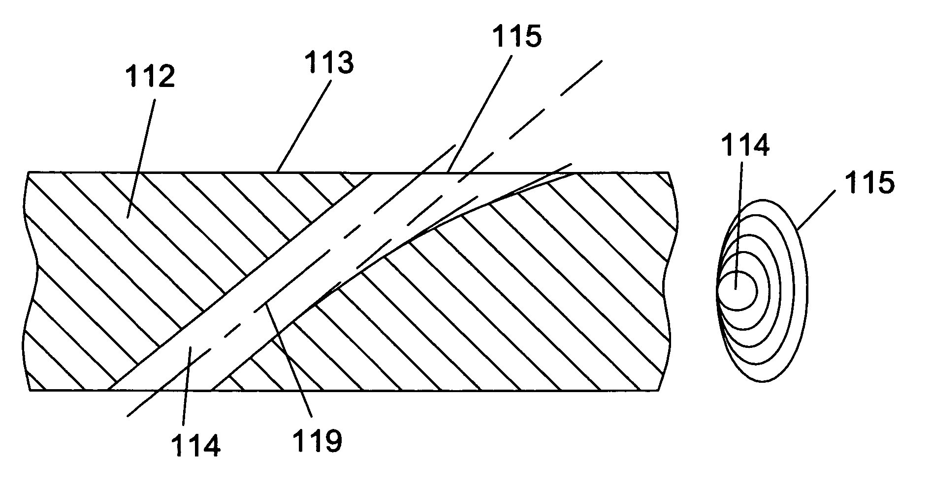
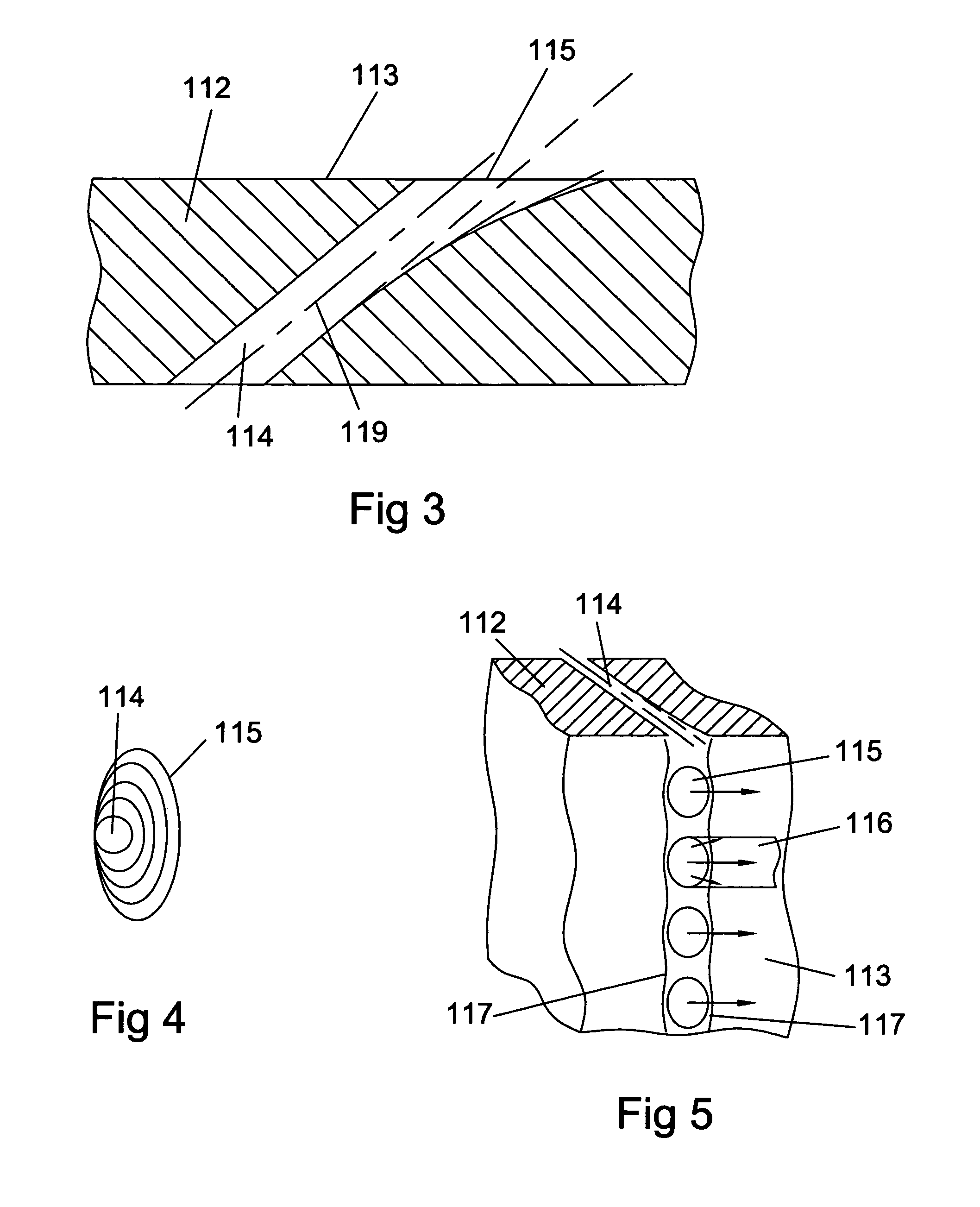
[0016]The film cooling hole of the present invention is shown in FIG. 3 in the wall of the airfoil 112. The film cooling hole includes a straight cooling hole portion 114 and a diffusion portion with a hole opening 115 onto the airfoil surface 113. A straight centerline of the cooling hole is represented by the centerline in FIG. 3. The upstream side of the cooling hole forms a straight line path through the entire film cooling hole. The downstream side of the film cooling hole follows a continuous curvature in the direction of the hot gas flow. A continuous curvature with respect to the centerline 119 of about 7 degrees begins from the straight hole surface to the hole opening 115. The constant curvature of the diffuser sides can range from about 7 degrees to about 13 degrees while still providing for the benefits of the present invention.

[0017]The sides of the film cooling hole also follow a continuous curvature outward from the hole centerline as shown in FIG. 4. The top of the h...


PUM


Abstract

A turbine airfoil with a plurality of film cooling holes having a diffuser having both stream-wise and spanwise expansion of the cooling air flow. The diffuser is formed from a series of ellipses with a gradual increase in the cross sectional areas in the flow direction. The diffuser has a stream-wise surface of continuous curvature of about 7 degrees, and both the spanwise outward surface and the spanwise inward surface has a continuous curvature of about 7 degrees. The upstream side surface of the diffuser is formed substantially along a straight line. The ellipse shaped diffuser has spanwise and stream-wise curved surfaces such that at the hole opening onto the airfoil wall, the hole has an elliptical cross sectional shape with the major axis in the spanwise direction of the airfoil.

Description

BACKGROUND OF THE INVENTION[0001]1. Field of the Invention[0002]The present invention relates generally to fluid reaction surfaces, and more specifically to film cooling holes in a turbine airfoil.[0003]2. Description of the Related Art including information disclosed under 37 CFR 1.97 and 1.98[0004]A gas turbine engine burns a fuel to produce a hot gas flow for the production of mechanical power. Compressed air from a compressor is mixed with a fuel in the combustor to produce the hot gas flow. The hot gas flow is then passed through a turbine having multiple stages of stator vanes and rotor blades to extract mechanical power from the flow. The engine efficiency can be increased by increasing the hot gas flow into the turbine. However, the turbine parts—especially the first stage stator vanes and rotor blades—are exposed to the hottest temperature and therefore the limiting properties of these parts determine the highest temperature entering the turbine.[0005]One method of increasi...

Claims


Application Information

Patent Timeline
IPC IPC(8): F01D5/18
CPCF01D5/186F05D2260/202F05D2250/00
Inventor LIANG, GEORGE
Owner FLORIDA TURBINE TECH
Why Eureka
Try Eureka